 Daniel Ansorregui
All the code and materials is in Github: https://github.com/DarkZeros/LightInk
Checkout the features demo video:
:
This project started long time ago in 2019, with the idea to build a solar watch that can use LORA packets to communicate to a receiver at home. Back then i started with a Heltec Wireless stick lite and an external eink display.
Then I discovered "Watchy" https://watchy.sqfmi.com/ and immediately bought one, it didn't have what i wanted (sleek design, LORA, and solar), however i though it was a very good foundation.
Back then, I contributed to Watchy many patches to optimize the display as much as I could, but at some point, that was not enough and new Hardware was needed. I tested Watchy + Solar cell and all I could get was 40 days of uptime:
Therefore i started creating my own board based on a DC-DC low quiscent current chip (TPS63900 1.8-V to 5.5-V, 75-nA IQ Buck-boost Converter). There were shortages, so the project weny idle for 2 years....
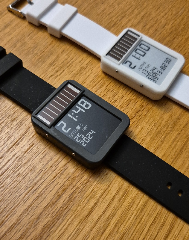
After receiving them in 2023 and when there was supply again, I started working on it. Build many PCBs that did not work, trying to get Touch+Solar+DC/DC+RTC+Display working. After many tests and trials (with many failures), I managed to have a watch working, using 2.7V only (the eink and the ESP32 seem to not care running on 2.7V), and the battery was 2 months (instead of 1 month of Watchy), with the solar giving an extra month (3 in total)!
Also because the watchy buttons were a PITA to work with, I decided to use the touch function in the ESP32, and that work quite well i have to say (also makes the case smaller).
I kept doing changes to the firmware, and my new HW, etc, until I hit a hard wall.
The ESP32 takes 28ms to boot, and that uses around 1mAs of current. About 60% of the total power was being used by the ESP32 just to boot (not to update or display anything).
This is the graph of typical GxEDP2 update with Arduino:
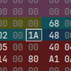
This is what i managed to get before hitting the wall (look at all that power in Booting from Flash!):
 The power usage is sadly not on any particular piece of code. Just on the flash sending the data to RAM in order to boot, so there is nothing you can do (other than remove most of the functionality and reduce the binary size to the minimum).
The wakeup stub is a function pointer set in RTC memory pointing to RTC memory itself, if set, the ESP core0 will call it during boot. This bypasses FLASH and everything entirely, the ESP32 boots there immediately in microseconds. However no function or code that is not in RTC can be run, for this reason eveything needs to be reimplemented, SPI (accesing the HW) display communication, etc.
Took me a couple of months, but finally managed to do it, reducing the power 2x, and getting into the ballpark of 6-10 months with a 100mAh battery. (The solutions of using wakeup stub is actually amazing, and i recomend for other projects as well, better than the ULP, you have access to all HW features, check https://github.com/DarkZeros/LightInk/blob/main/firmware/main/deep_sleep.cpp and https://github.com/DarkZeros/LightInk/blob/main/firmware/main/uspi.h)
And finally, this is the result, how the consumption looked with the boot part removed:
I implemented code to handle the SPI communication and to update the region of the display controller buffer. With this I could boot+send+update display in less than 1ms. Also, I could just power of the ESP32 to deep sleep again, while waiting for the display to update, saving me 1mA on light sleep!
With this I finally managed to have a watch with a battery running 9 months (until I decommission it for a newer HW).
Since then I have polished the code, the case, added LORA (yeah!) even GPS (was a bad idea), and I am still building the project up.
But I think this project has good ideas (Touch, wakeup stub, eink driver) that can benefit the community so I would like to share it. And if possibly receive feedback from other people...
Read more »


 TheCatwoman
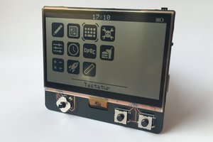
 Max.K
Max.K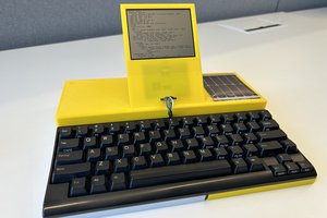
 Andreas Eriksen
 Frank Buss
This is beautiful!