 mircemk
An electronic codelock is a security device that grants access using a numerical sequence—a PIN code—rather than a traditional physical key. These systems are common in offices, apartment complexes, and increasingly, modern "smart" homes.
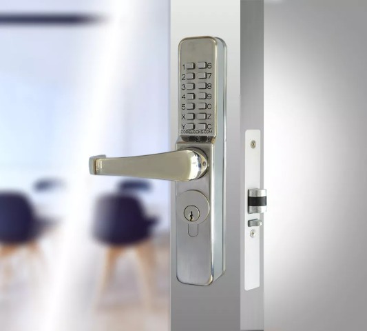
In some of my previous videos, I described several different ways to make a simple electronic codelock. This time I will show you how I developed and built a prototype for a real code-lock, which in its characteristics is much more advanced than many commercial devices of this kind.
The test prototype contains a real mechanical lock with standard dimensions. During the development, I gradually solved the problems one by one. I decided to use standard components that are easily available on the market and are relatively inexpensive.
Here is what the mechanical-electronic part looks like, made on a plastic board for greater visibility and easy modification if necessary during development.
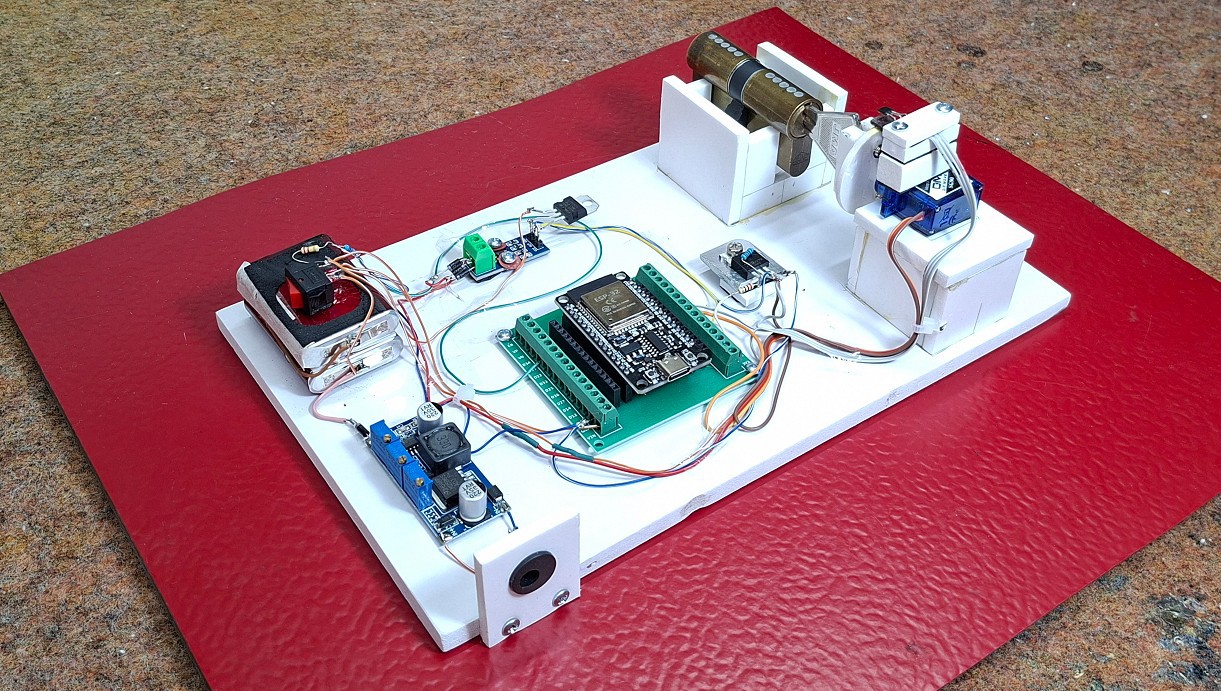
I'll start with the electronic components:
- The heart of the lock is an ESP32 MCU board specifically placed on a suitable socket adapted for easy modification without soldering.
- Then a battery pack of two series-connected Li-Ion batteries that provide a voltage of 7 to 8 V.
- At the moment I didn't have a charger for such batteries, so I used this Constant current/constant voltage stabilizer. I set the output voltage to 8.4V and the constant current to 0.6A. In this way, the board successfully performs the task of a charger.
- Then we have two resistors in a voltage divider connection that bring the appropriate voltage level to the D2 pin of the MCU. In this way, the battery capacity is measured.
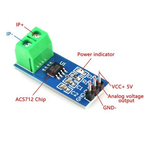
- Small board is an ACS712 current sensor and serves to protect the Motor. The sensor measures the current through the motor and if it exceeds a predefined maximum value (this happens for example if the lock gets stuck and stays in one place), then the MCU turns off the voltage supply to the motor.
- Next is a 5V regulator that provides power to the current sensor and the Hall effect sensor.
- Small cooler has a MOSFET transistor mounted with two resistors and its purpose is to turn off all circuits when the lock is idle. This way, huge battery savings are achieved, which is crucial in this type of device.
- Next comes a very important part, which is a combination of a Hall effect sensor and a permanent magnet, which determines the initial home position of the key. This greatly simplifies and secures the way the MCU controls the lock.
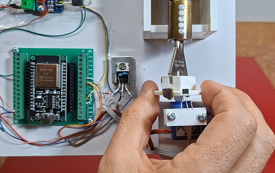
- And finally, the motor that moves the key in the lock. In this prototype, I use a small, cheap servo modified in a way that it can move continuously in any direction. We will not dwell on the method of modification here because it is explained in detail in many videos and the procedure is relatively easy. I chose this particular way of moving the lock because of its universality. If in the final product we use a larger servo with metal gears, then there is no need for any changes to the code, but also with minimal changes, a brushless motor with a bidirectional driver, or a regular motor with an H-bridge driver can be used.
- I also made a special bearing for the lock, so that the motor can move the key left and right, so that we have approximately realistic conditions during testing.
- Otherwise, all this electronics, using SMD components, can be placed on a PCB slightly larger than an MCU dev board.
Now let's move on to the software part. The code is made in a way that almost every phase of the lock's operation can be changed at the very beginning without having to walk through the entire code.
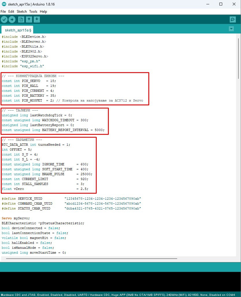
This is a crucial requirement in this type of development project, because very often when testing and changing components, quick changes need to be made to the code. I will describe all the variables that can be changed directly, as well as their functions in the circuit:
- At the beginning, all 5 pins of the ESP32 used in this project are defined.
- Then comes...