 Nelectra
Overview
Heliotrax is a solar-powered, battery-less IoT platform designed for long-term outdoor operation. It enables reliable monitoring and control of sensors and actuators without the need for batteries or regular maintenance.
The system is built as a modular hardware platform for developers and system integrators, providing robust electronics and reference firmware while allowing full flexibility in software implementation.
The Problem
Many outdoor IoT systems rely on batteries, which introduce limitations in lifetime, reliability, and maintenance. In remote or hard-to-access locations, battery replacement becomes costly and impractical.
In addition, most solar-powered IoT nodes are designed only for low-power sensing. They can supply sensors requiring small voltages and minimal current, but are not capable of driving actuators.
There is currently a lack of compact systems that can:
- harvest energy from small solar panels
- store energy efficiently
- deliver short, high-power bursts (e.g., up to 24V)
This limits the ability to control actuators such as latching solenoids, valves, or switching elements in autonomous outdoor system
The Solution
Heliotrax combines solar energy harvesting with efficient energy storage and controlled high-power delivery.
Energy is stored in two 22F supercapacitors connected in series, forming a storage stage up to 5V. The system accumulates energy over time and releases it as a controlled high-power burst when required.
This enables:
- battery-less operation
- long-term autonomous deployment
- actuation of power-hungry devices
The platform bridges the gap between low-power energy harvesting and high-power actuation.
System Architecture
Transmitter Node (core hardware)
- solar energy harvesting and storage
- ultra-low quiescent current (~tens of µA)
- sensor interfacing and data acquisition
- controlled high-power output for actuators
- wireless communication
Receiver Node
- implemented on standard ESP32-C3 boards (e.g., XIAO, Dev Module)
- receives data and triggers actions
- requires only corresponding software
Performance & Technical Capabilities
- Energy storage: 2× 22F supercapacitors (series, up to 5V)
- Ultra-low quiescent current: a few 10 µA
- No-light operation: up to ~5 days (foggy conditions, ultra-low-power mode)
High-power burst outputs:
- 24V @ 500 mA
- 12V @ 1 A
- 9V @ 1.5 A
Expandability:
- Additional supercapacitors or Lithium-Ion Capacitors via screw terminals
- External solar panel or alternative energy source input
Hardware Platform Features
- Modular hardware design
- 7 Grove connectors for sensors and modules
- Support for Grove ecosystem (e.g., LoRa modules)
- Interface for SIM800L GSM/GPRS module
- Designed for flexible integration and prototyping
Software Approach
Heliotrax follows a hardware-first approach.
The project provides:
- reference firmware (Arduino-based PoC)
- example implementations for transmitter and receiver
Users are expected to develop their own application software based on their requirements, ensuring full flexibility and independence from predefined ecosystems.
Why It Matters
Heliotrax extends the capabilities of autonomous IoT systems beyond sensing by enabling actuator control without batteries.
Key advantages:
- maintenance-free deployments
- operation in remote or hard-to-access locations
- reduced environmental impact
- ability to drive real-world devices (e.g., valves, relays, actuators)
This makes it suitable for applications such as:
- water management systems
- infrastructure control
- distributed automation in outdoor environments
Documentation & Code
Reference firmware is available on GitHub: https://github.com/Nelectra/Heliotrax-reference-firmware
The repository includes transmitter and receiver implementations for testing and development.
Project webpage: https://heliotrax.io/
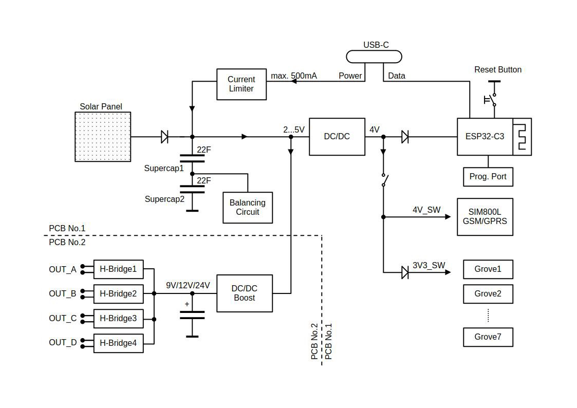
Technical Specifications
PCB No.1 – Control and Communication
Energy storage:
- Onboard 2x supercapacitors 22F/2.8V
- Expandable with an additional pair of supercapacitors (screw terminal connection)
Solar panel input:
- Default 5V/60mA 45x45mm solar panel
- Expandable with an additional independent power source (decoupled by diodes),e.g., a second solar panel
DC-DC controller:
- Input voltage range: 1.7V-5.5V
- Output voltage: 4V
- Max output current: 2A
Switched Power Outputs:
- GSM/GPRS Modem SIM800L: 4V
- Grove interfaces: approx. 3.3V
Controller:
- Type: ESP32-C3-MINI-1-N4
- External 32 kHz crystal for RTC in deep sleep mode
- Reset button for firmware flashing (prevents entering sleep mode via software)
Programming Interfaces:
- UART (RX, TX, ENABLE, BOOT, supercapacitor voltage)
- USB-C (data + power, 500mA current limited)
Grove interfaces:
- 7x connectors (2xSPI, 2xADC, 2xI2C, 1xUART)
- Supply voltage: approx. 3.3V
- Supply current limited only by DC-DC controller (approx. 2A)
PCB No.2 – Power and Actuation
Boost DC-DC Converter:
- Input voltage range 3.0V – 5.5V
- Max. input current 6A (peak)
- Output voltage: 9V/12V/24V
- Output capacitor approx. 500uF
Max. Output Current:
- 1.5A @ 9V
- 1.0A @ 12V
- 0.5A @ 24V
Outputs:
- 4x H-Bridge outputs (positive, negative, high impedance)
- Overvoltage protection (TVS diodes)
Control:
- I2C commands (4-output variant)
- Digital I/O (1-output variant)