 Ilya Egorov
The mPCIe Sensor Module in Action
In the previous log I introduced the air quality sensor module — now it's time to actually read data from it. The module carries three sensors over a shared I²C bus: BMP280 (temperature + pressure), AHT20 (temperature + humidity), and ENS160 (eCO₂, TVOC, AQI index). All three sit at fixed I²C addresses and are powered through the mPCIe connector from DevPocket's 3.3V rail.
Reading the Sensors — How the Script Works
On startup, the script runs an I²C scan and initialises each sensor in sequence, printing the result to the console.The ENS160 is the most demanding sensor to initialise — it requires a hardware reset sequence (RESET → IDLE → CLEAR → STANDARD), and its Part ID (0x0160) is verified before proceeding. Once running in standard mode, it receives live temperature and humidity compensation data from the AHT20 on every reading cycle, which is mandatory for accurate eCO₂ and TVOC figures.Readings are updated once per second. The console microREPL output looks like this:
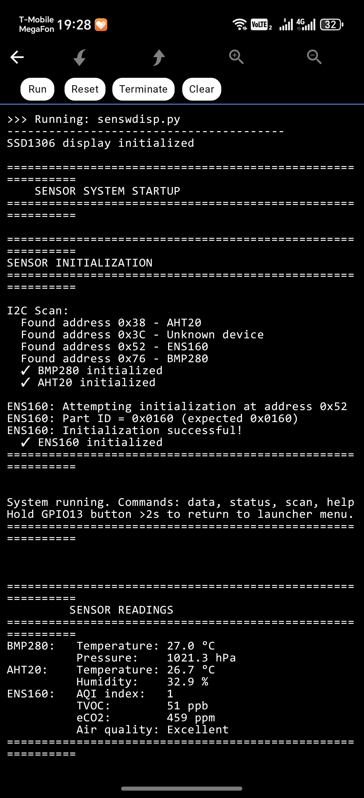
(Screenshot: console output with sensor init and live readings)
While the script is running you can interact with it via micro-REPL or any serial terminal:
| Command | Action |
|---|---|
data | Print a fresh sensor reading immediately |
status | Show which sensors were found and ENS160 init state |
scan | Re-run the I²C bus scan |
help | List available commands |
The four WS2812B LEDs on DevPocket each have a dedicated role in this script:
| LED | Meaning |
|---|---|
| LED 0 | Green — all sensors OK / Red — at least one missing |
| LED 1 | Orange — USB charging in progress / Green — on battery |
| LED 2 | Blue blink — I²C read cycle active |
| LED 3 | Green — air quality normal / Yellow — warning / Red — poor |
Going Fully Standalone — The Display Lid
When I designed DevPocket I included two dedicated connectors on the main board: one for an OLED display and one for an LED matrix. The idea was to make a PCB that mounts inside the top lid of the enclosure — when you close the case, the connectors mate automatically and the display(LED matrix) is live without any extra wiring.
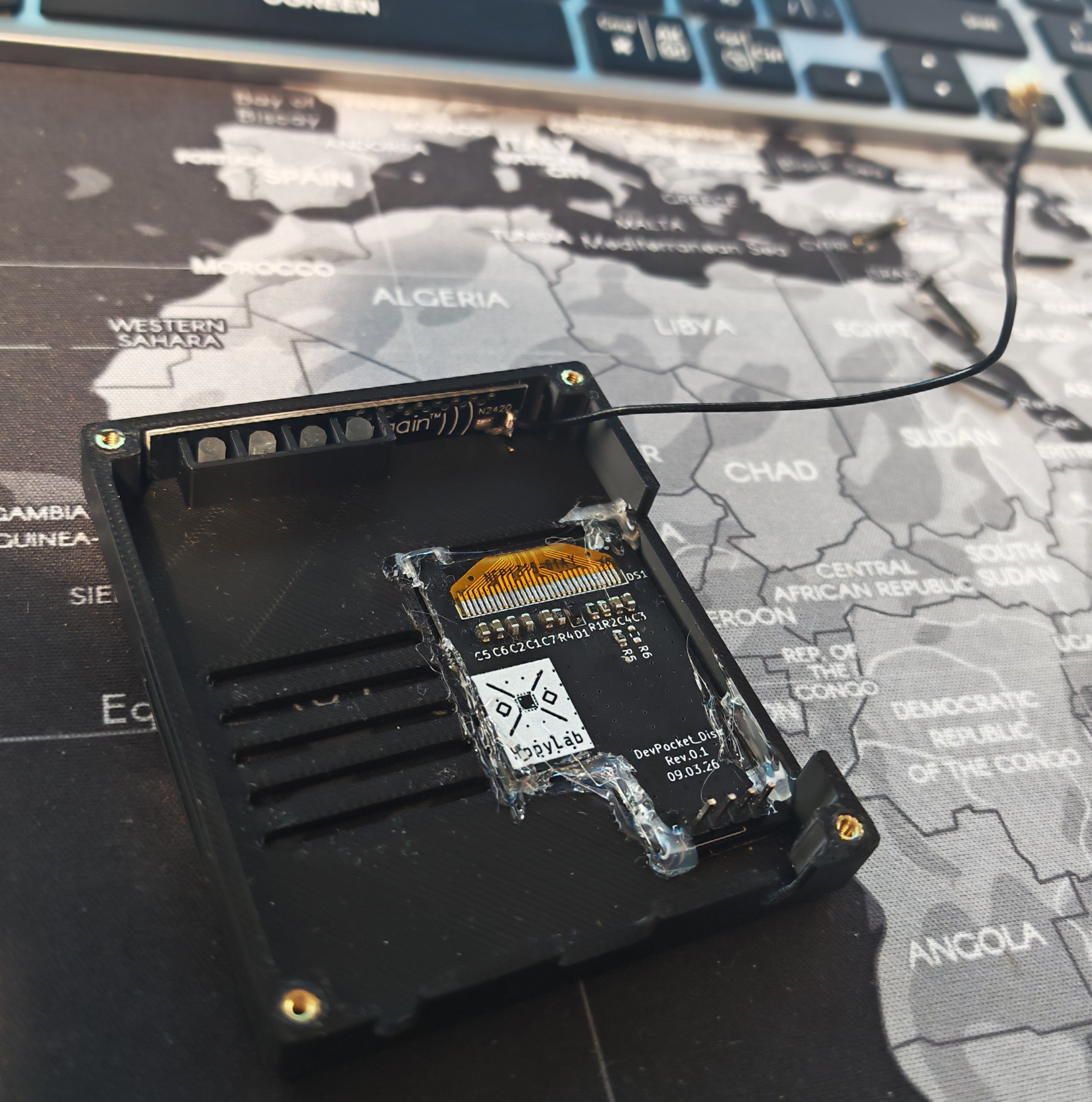
(Photo: top lid with the display board glued in)
The display board uses a standard 128×64 SSD1306 OLED. It connects to the I²C bus as the sensor module, so the whole system — sensors, display, and main MCU — runs on two wires.
The OLED layout for the air quality script fits all key data on the 64px height.Temperature and humidity sit on the top line, pressure on the second. Below the divider: AQI, TVOC, eCO₂, and a plain-English air quality description. The bottom status bar shows either a sensor warning (!Sensor miss), charging state, or the button hint (Hold>2s=menu).
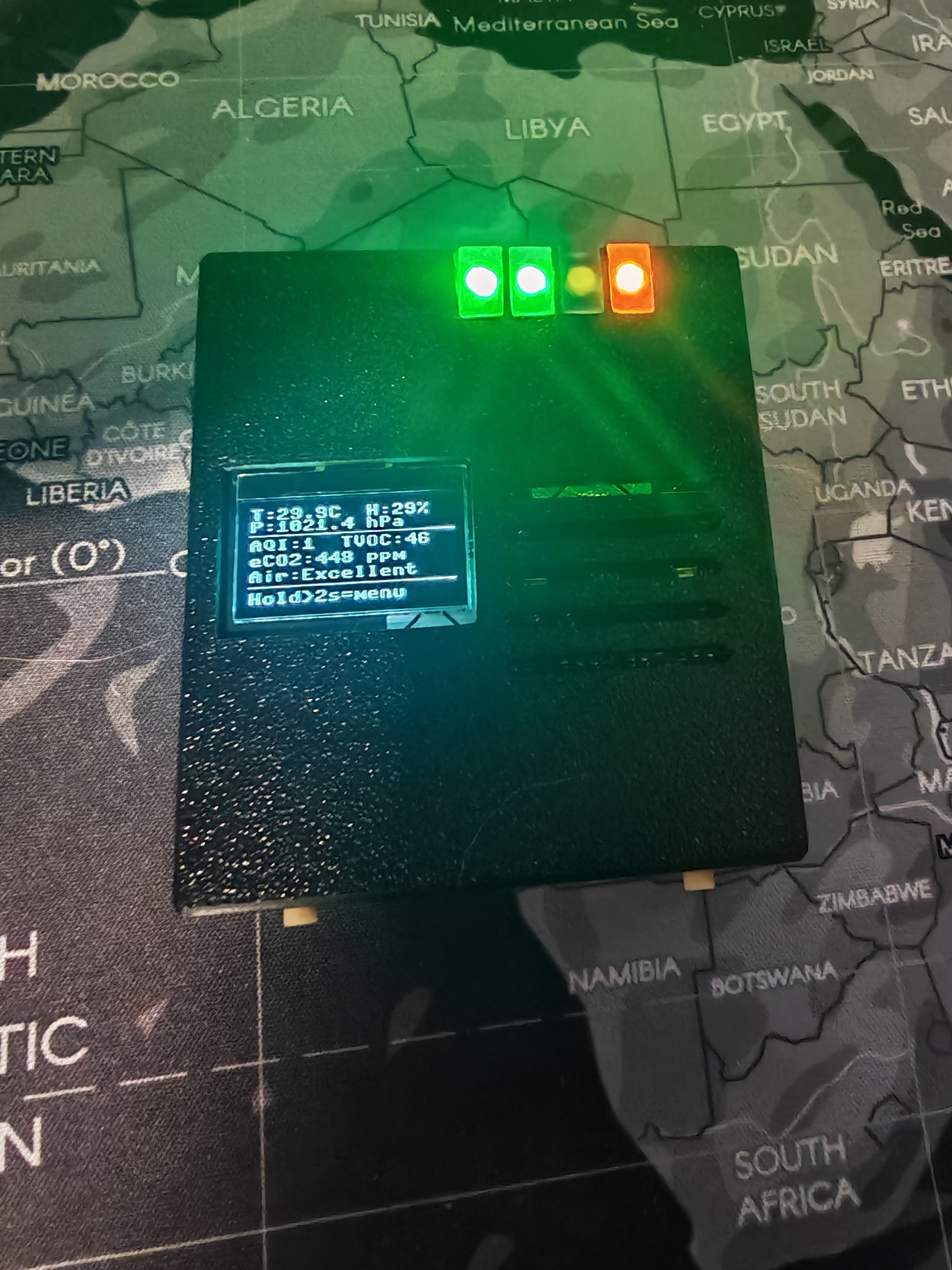
(Photo: DevPocket with the sensor module and display running)
Returning to the Launcher
Since this script runs inside the launcher (described in Log #2), exiting back to the script menu is built in. Holding the NEXT button (GPIO13) for more than 2 seconds triggers a clean shutdown: the sensor power rail is cut via the PWR_SENSORS GPIO, the OLED shows "Returning to menu…", the LEDs are cleared, and a KeyboardInterrupt is raised — which the launcher catches and uses to return to the script selection menu. No reboot needed.
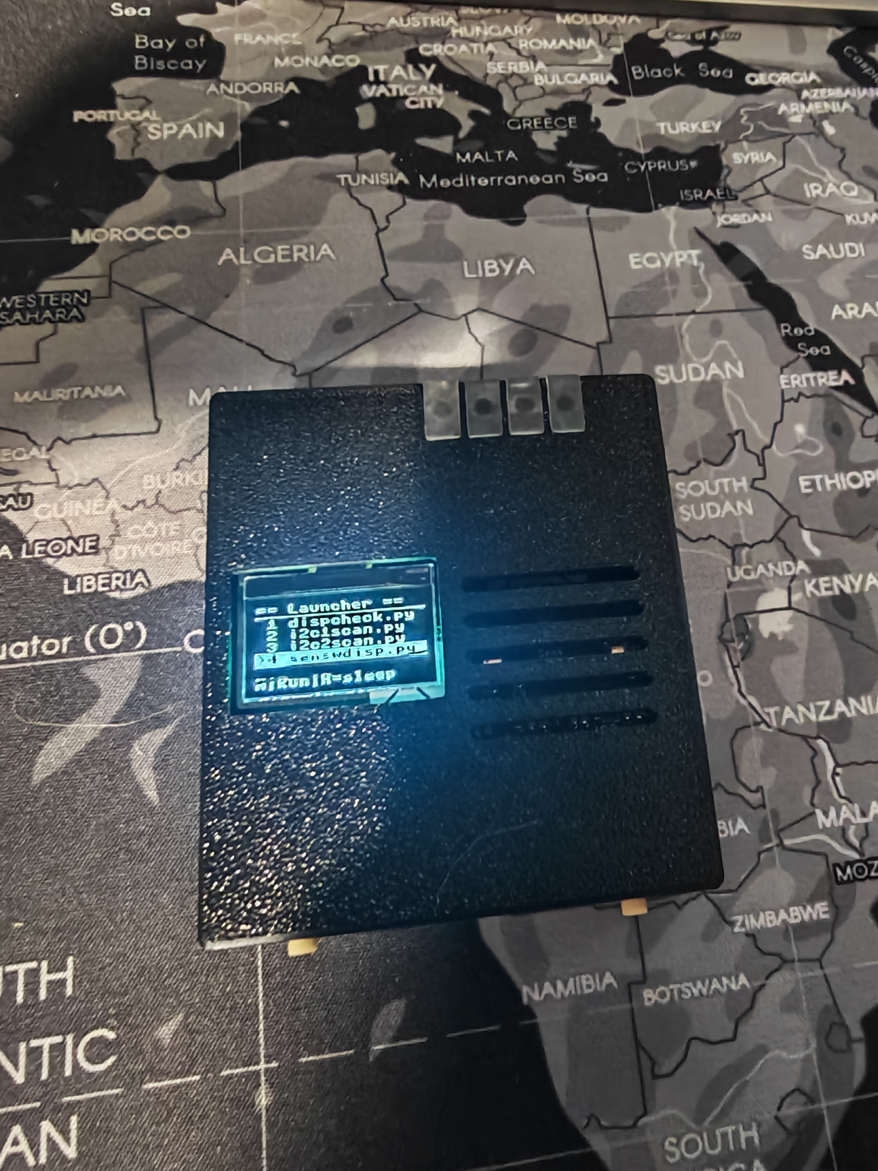
(Photo: DevPocket with display in the script selection menu )
What This Actually Gives You
At this point DevPocket is a fully self-contained device: battery powered, display on the lid, no phone or PC required. In practice I carry it as a portable air quality monitor — drop it in a bag, pull it out, and the OLED immediately shows temperature, humidity, pressure, CO₂ level, and an AQI rating for wherever you are. The same unit also doubles as a battery-powered I²C scanner — just launch the scanner script from the menu instead.
What's Next
In Log #4 I'll cover the mechanical side — how the enclosure is designed and assembled, and I'll publish the STEP models for the current enclosure revision to GitHub so you can print or modify your own.
Discussions
Become a Hackaday.io Member
Create an account to leave a comment. Already have an account? Log In.