 László SZŐKE
1. The $10,000 Problem in Automotive Diagnostics
Finding a broken wire or a short circuit in a modern automotive wiring harness (such as a CAN-bus network) is incredibly frustrating. Mechanics usually face two choices:
- Strip the entire dashboard and manually trace the wires (guessing and checking).
- Buy a proprietary, industrial Time Domain Reflectometer (TDR) that can easily cost upwards of $10,000.
We wanted to democratize this process. We realized that the hardware required for precise signal processing is already mass-produced and sits on everyone's desk: a standard USB sound card.
2. The Core Hack: Audio-Driven TDR
Traditional TDRs send a sharp electrical pulse down a wire and measure the time it takes for the echo to return (Time-of-Flight). This requires very fast, expensive hardware to measure nanosecond differences.
TraceVena takes a completely different approach. We use cheap C-Media USB audio chips, which have surprisingly robust ADCs and DACs optimized for audio frequencies. Instead of a pulse, we transmit a continuous 4kHz or 8kHz sine wave down the suspect cable. We then "listen" to the reflection. The parasitic capacitance of the cable causes a minute phase shift in the sine wave. By measuring this phase shift, we can calculate the distance to the fault.
3. Hardware Architecture (The Frugal Interface)
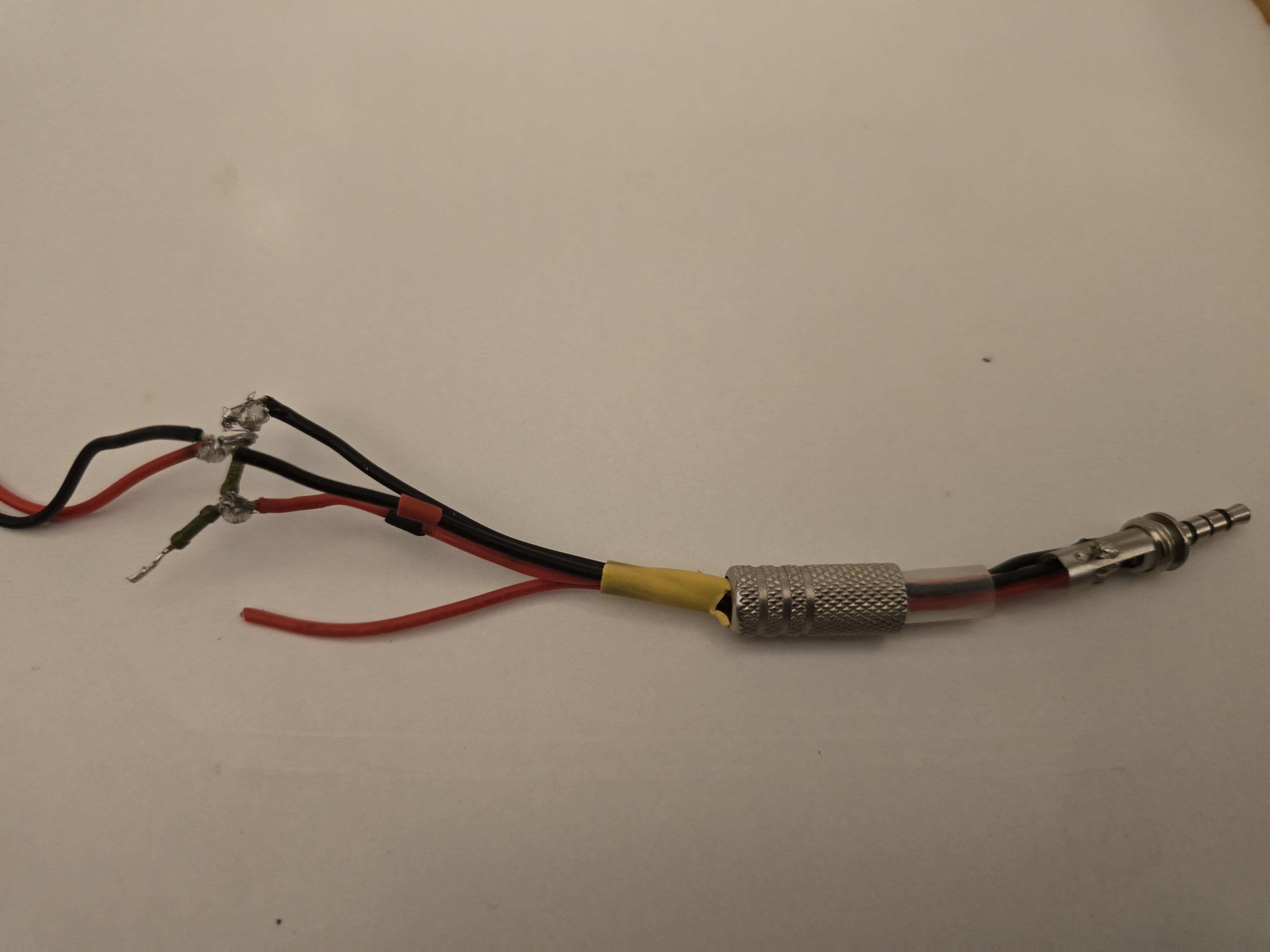
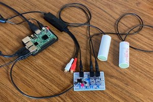
You cannot plug a car's 12V or 24V electrical system directly into your laptop’s microphone jack. To make this work safely, we designed a minimalist, $5 analog interface (currently built on a perfboard) that acts as a hardware firewall and measurement bridge.
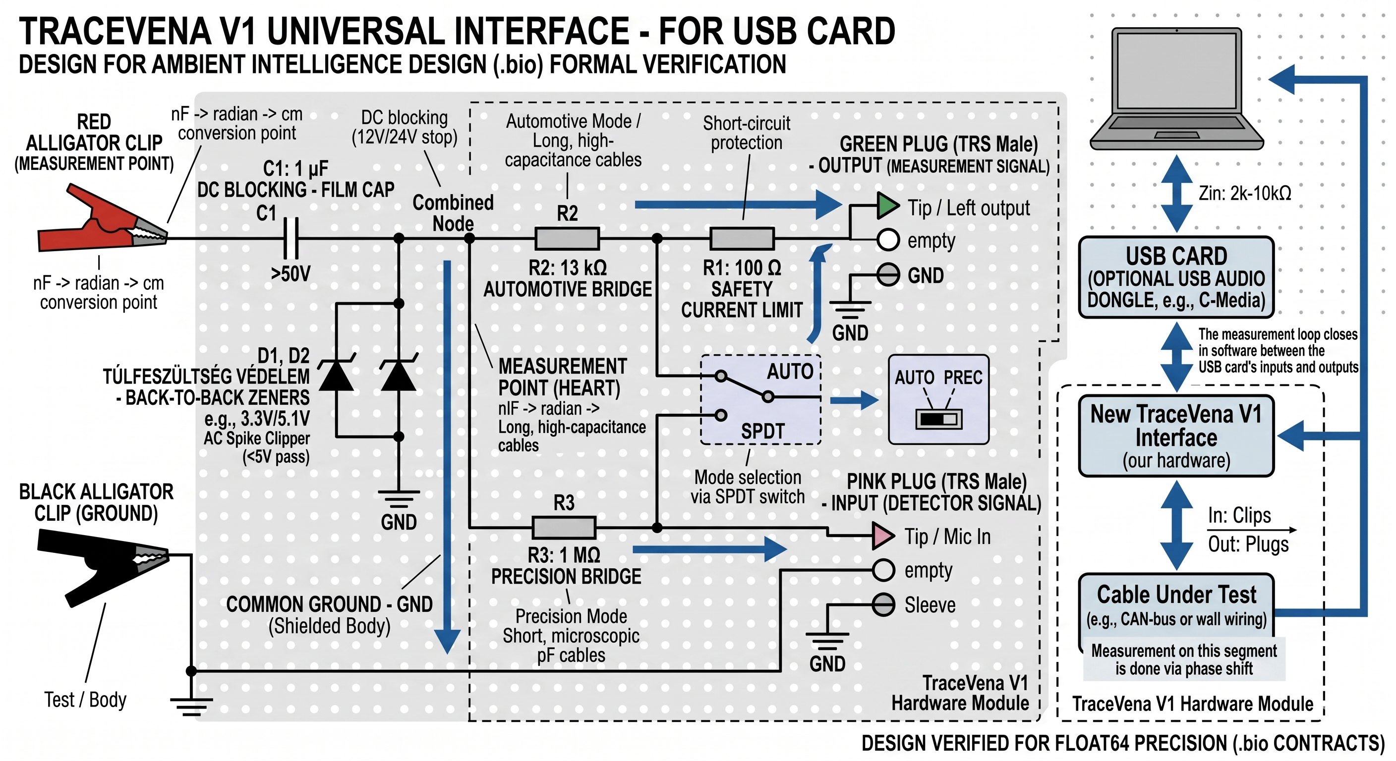
Key Components of the Interface:
- The Measurement Bridge (SPDT Switch): We use a toggle switch to change the measurement range. The "AUTO" mode uses a 13 kΩ resistor (R2) for long, high-capacitance automotive cables. The "PREC" mode uses a 1 MΩ resistor (R3) for short, micro-pF precision wires.
- The DC Blocker: A 1 µF Film Capacitor (C1) sits right at the input. We specifically use film (not ceramic) because its capacitance remains perfectly stable regardless of the voltage. It blocks 12V/24V DC from frying the system, allowing only the AC measuring signal to pass.
- The Overvoltage Protection: Two 3.3V Zener Diodes (D1, D2) are placed back-to-back to instantly clip any high-voltage AC spikes before they reach the soundcard.
4. The Software Brain (MetaSpace Engine)
When pushing a signal through a 1 MΩ resistor, the return amplitude drops massively, approaching the quantization noise floor of a cheap soundcard. A standard audio driver would just treat this as background noise.
To solve this, we bypass standard audio processing. Our custom software engine uses Float64 precision and a highly optimized Goertzel algorithm to extract the exact phase of the 4kHz/8kHz signal from the raw audio bitstream.
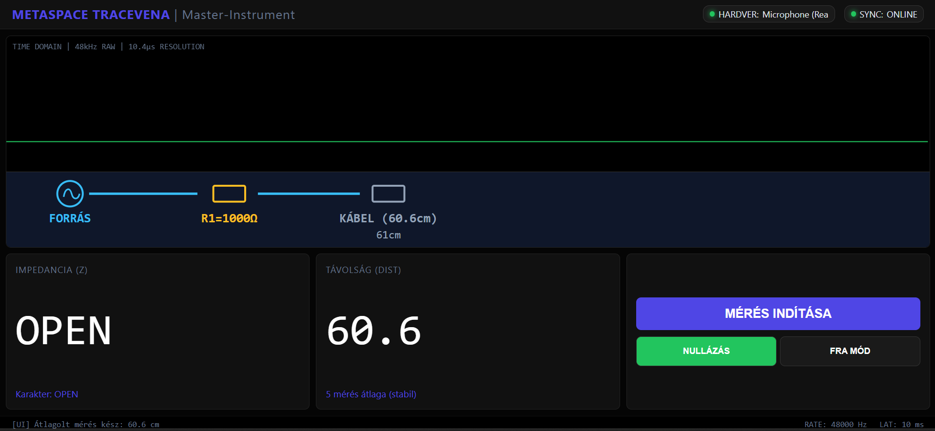
More importantly, the software uses deterministic logic (via the Z3 SMT solver). It dynamically calibrates itself to the parasitic capacitance of the hardware firewall (the capacitor and diodes), setting that as the absolute 0.00 cm baseline. If the signal-to-noise ratio drops too low, the formal verification layer acts as a fail-safe: it formally proves the measurement condition is unmet rather than wildly guessing in the noise.
5. Next Steps
We are currently soldering the final V1 perfboard prototypes and preparing to take them out to the garage for real-world field tests on actual damaged vehicle harnesses. Stay tuned for the project logs!

 Gregory
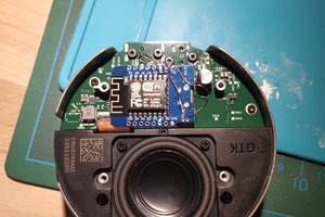

 mircemk
 SingularitySurfer
Hi everyone! Thanks for checking out TraceVena.
I’m currently moving from my 'janky' TRRS prototype to the V1 perfboard. The biggest challenge I’m facing is the 1 MΩ measurement bridge; pushing a sine wave through that much resistance puts the return signal right at the quantization noise floor of a standard C-Media ADC.
I’m using a massive 16,384-sample integration window and a Z3-based fail-safe to prove the phase shift, but I’d love to hear your technical critique on the analog front-end. Specifically, do you think the 1 µF film cap and back-to-back Zeners will introduce too much parasitic drift for cm-accurate TDR, or is my software-based baseline calibration enough to compensate?
Looking forward to your thoughts and 'destructive' criticism!