 Retep V
With my requirements and stretch goals set out, I fired up Kicad and started to pull in components until I had basically more or less replicated a mix between the FabGL Serial Terminal and the uTerm2-S. However, I wanted to have a way of switching the serial connection between normal and null-modem.
I found that real crossbar ICs that could handle 12V were extremely expensive. I considered the venerable 4066 analog switch, and other analog switches. But then stumbled on a post that was talking about a circuit controlling a bistable relay with only one GPIO port. That was interesting enough for me to try out, and after buying some relays and prototyping, I got it working quite stable within parameters. The relays were surprisingly cheap, and I was up for experimenting. So I chose to use relays.
But relays use a lot of current when they are being powered. So I chose to use latching relays. But that had yet another problem. The small ones are single-coil latching relays and are set one way by applying a pules with a specific polarity, while they are set the other way by applying a similar pulse, but with reverse polarity. That requires two GPIO pins, and I did not have enough.
Another option would be to use a circuit built around two comparators, and use one GPIO pin in tristate mode.
But then I stumbled upon a really simple circuit, once patented by Omron, that could do the same with one GPIO pin, but not using tristate mode, built around a transistor, two diodes, a resistor and a large capacitor. It can be seen here on page 12, section 2.2.24.
I started experimenting with the circuit on the breadboard, and it worked fine. I measured currents, and it all seemed within specs of the ESP32's GPIO port, so I went for it.
I designed the PCB fully, and sent it off to JLCPCB for the ridiculously low price of €11.01.
After a few days the boards arrived, and I started soldering! Everything went smooth, except for soldering that pesky CP2102 . USB worked, I could program the firmware, got VGA out, keyboard and mouse were working, and after programming some lines to switch the relays... No clicks, no switching.
:(
So that led to taking out the oscilloscope and trying to find out what was the problem. That is described in the Github entry of the nTerm2-S, and I would refer you to there if it interests you.
After a while, my beautiful board turned into a Frankenstein. Not helped by the fact that I only had ESP32s that were soldered onto a carrier board, decided to desolder one, ripped of an important pad, and had to perform microsurgery to solder a wire onto it :D.
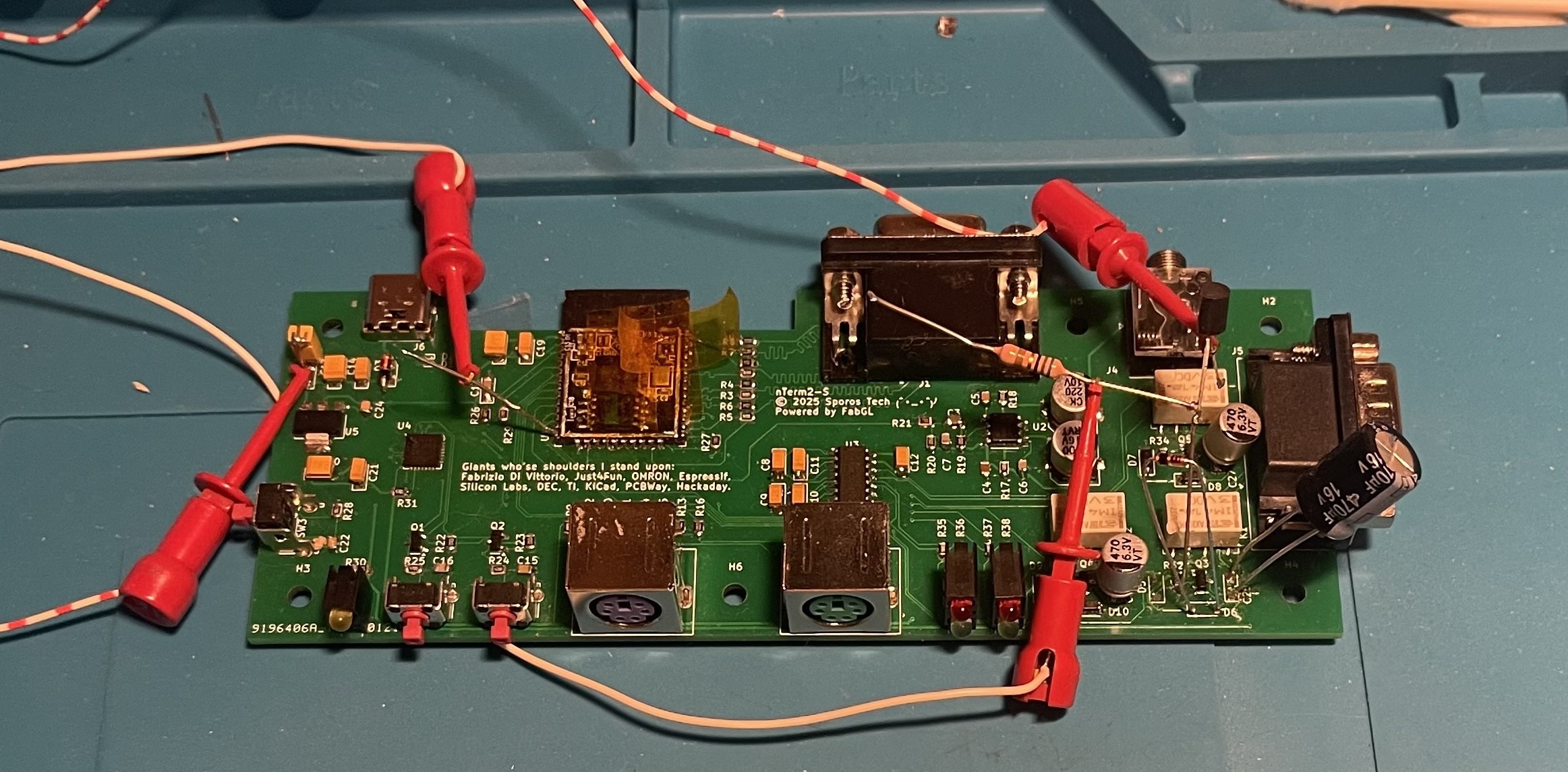
In any case, a few more redesign steps had to be taken, and at some point I reached v0.5.
Discussions
Become a Hackaday.io Member
Create an account to leave a comment. Already have an account? Log In.