 Retep V
The v0.5 was actually such a success that instead of tearing the whole project down with my switch to the FT231, I decided to clone the project into a new Github repository and name it nTerm2-S-FT231. I'm not sure that was actually the best thing to do, but here we are.
While testing v0.5, another thing had started to annoy me. I had started to write the software, and at some point got the status bar to work. And I was showing the date and time on the status bar. But every time I cycled the power, I had to set the clock again. Not ideal, so I started looking for an RTC chip. Now, I had all of the GPIOs in use, except one. So if I would want to add an RTC without making changes to the GPIO or surrounding circuitry, I had to find something that used one wire. 1-wire! I shopped around on Dallas's website and found the DS417. Not really an RTC, but a 64-bit counter that increases the count with 1 every second. Sounds like Unix time_t to me, so perfect. Cobbled a prototype together on my v0.5 board, and it worked first time.
Next up was removing the CP2102 from the design and putting the FT231 in. That was a major undertaking, but went well. I also got smart on the TVS diodes and used a chip that had everything inside it to protect the USB lines.
After I got that done, it was time for the RTC. The RTC's clock circuit had quite some requirements for the PCB design. Especially large copper fills around the crystal.
At the last moment I added solder bridges to the circuit, so that people could decide what they want to populate or not. Bridges for bypassing the amplifier and bridges for bypassing the relay circuits.
The rest of the changes were again a few wrong footprints. A few commits later, I arrived at v0.08, and sent everything off to JLCPCB again.
The next day I was already sorry that I had jumped that gun, and had a v0.09. But there you go, v0.08 was the next version that got life breathed into it. Here's a nice close-up pic of the FT231 and the RTC clock circuit (not populated yet).
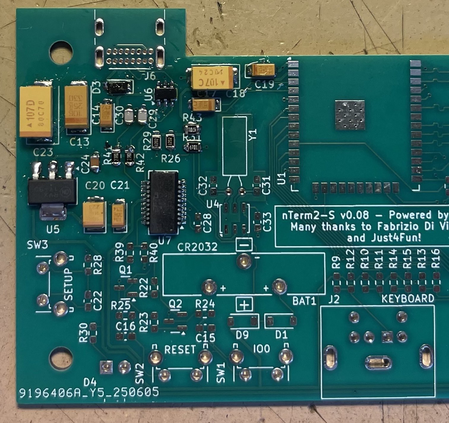
Now, I want to point your attention to capacitor C19, at the top right. See how its orientation is different from all the other capacitors? That's a recipe for disaster, because for sure there will be people (including myself) who will solder it the wrong way around. This is a major showstopper, unacceptable and cannot be released this way.
But other than that, this release was great, it worked flawlessly, the clock worked, all the footprints were finally right. Just that pesky capacitor that I should have rotated. Great success!
Or, once again: so I thought.
Discussions
Become a Hackaday.io Member
Create an account to leave a comment. Already have an account? Log In.