 Dave
Ok I but my big boy pants on and actually made a start on the Excalibur 64 Original build. My initial idea was to build it stages. Starting with the oscillator, then CPU, ROM/RAM, then move further out to the I/O and finally video.
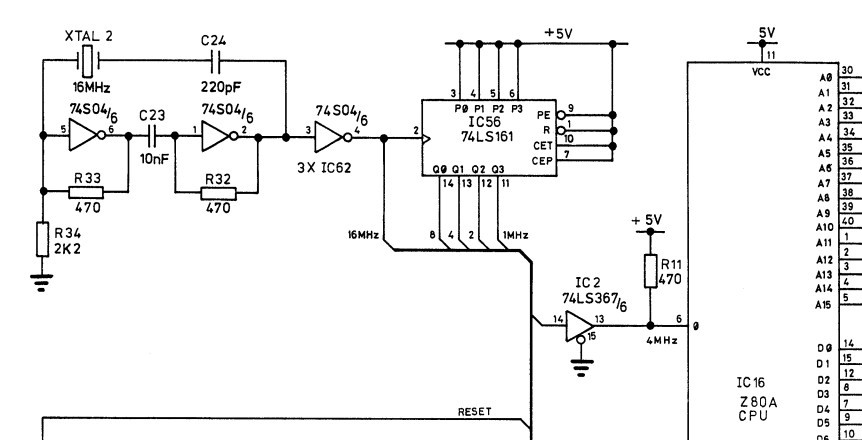
But I didn't have quite the right ICs for the oscillator. It needed a 74S04 for amplification and phase control and a 74LS161 to divide the 16Mhz crystal. Only had a 74LS04 and a 74HCT161. Discovered these are no good. The oscillator circuit is a two-inverter series-resonant crystal oscillator. The two inverters provide a 0 degree phase shift. The problem is the 74LS series has much less drive capability compared to the 74S series. I could muck about with the 470 resistors to reduce the load but I want to keep it as original as possible. So will have to leave the oscillator for the next bits order. So figured might as well start installing all the IC sockets. Which is quite therapeutic.
This the two-inverter series-resonant crystal oscillator
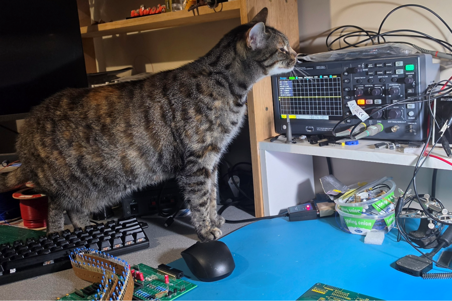
I thought it best to conduct a cat scan before declaring I had the wrong ICs
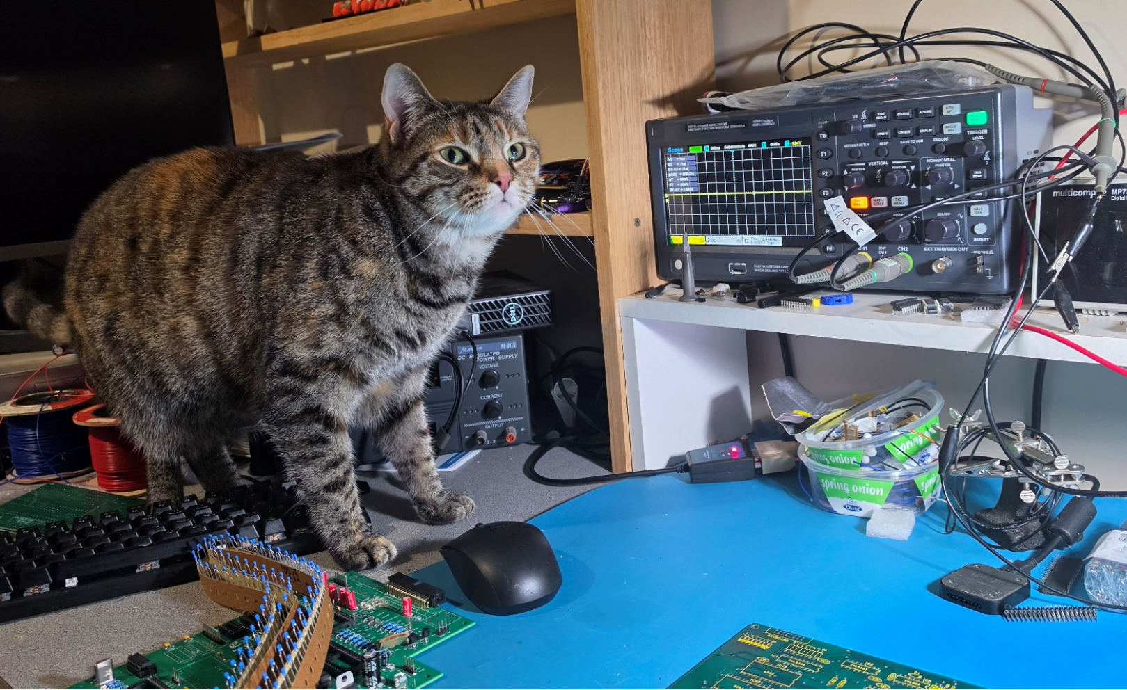
Reading her facial expression it's confirmed 😒 need the right ICs
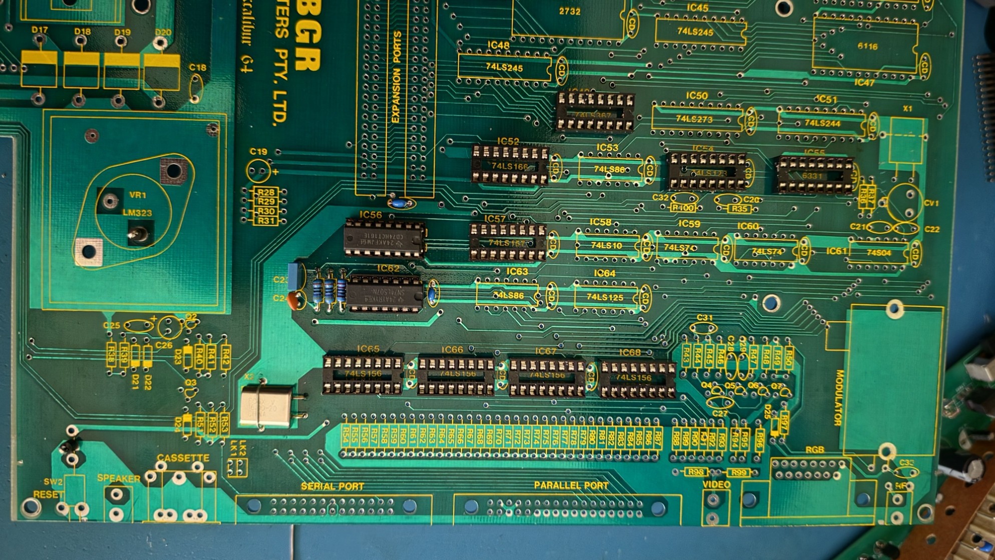
And the progress so far - not too exciting but will be!!
Discussions
Become a Hackaday.io Member
Create an account to leave a comment. Already have an account? Log In.
The low-level input current of the S04 is about 2 mA. The 470 ohm resistors are a bit too much, try 330 or 360 ohm in their place. There is also a single inverter variation of the crystal oscillator circuit, should you need an inverter elsewhere in your circuit. ON Semi's appnote AND9983 covers TTL/CMOS oscillators and their pitfalls. It has been handy to have around.
Are you sure? yes | no
Thanks Darrin, I had a read of the app note. It's interesting what you can do with just a few inverters. I might have to tinker with it for my own designs. But for this particular project I'm building this board for someone else. The PCB here is the one he bought in the mid 80's and never got around to building it. So in this case I want to keep it as close to the original design.
Having said that you have a point with the resistors, physically no one would notice the difference. I am already aware of some other design flaws. Such as the audio circuit which uses a LM348 with a BC548 in an emitter follower configuration to directly drive a 8 ohm speaker, no AC coupling. As part of my own recreation I built it as the the designers intended. It sounded ok but the transistor got very hot. There is a mod from back in the day that fixes this problem. So in this case modifying the circuit would still be period correct and doesn't burn out a poor old BC548.
That's a long way of saying I'll try different values to get a clean square wave
Are you sure? yes | no
I took a second look to discover that I reversed your meaning. Thinking that you were using a 74S in place of the 74LS. Recalculating for a LS type, I get 1.5k across the inverters, and a 13k to gound. That would use about half of the LS04's 400uA high level output current. But at 1.5k, a low on the output could not pull the input low again. A conundrum.
Are you sure? yes | no
Mmmm interesting I have often used the 14 and 8 pin wide DIP CMOS/TTL oscillators. Quick look on Digikey and they don't have a 16Mhz and the others in the package are obsolete. Doesn't mean they are not obtainable just need to look further than the usual mobs. Thanks 😊
Are you sure? yes | no
You can also use the square cans with one more jumper.
Are you sure? yes | no
Forget about the 74S04 and install an active 16 MHz oscillator can which fits in the same DIP-14 space. Pins 14 and 8 are VCC and GND. The output will be on pin 8 which looks unused, only half of the S04 is used, so jumper it to pin 4.
Are you sure? yes | no