 CiferTech
🧠 The Idea — Indoor Positioning Without GPS
Indoor positioning is one of those problems that looks easy until you actually try to solve it, because the moment GPS drops out, you’re forced to rely on indirect measurements that are often noisy, inconsistent, and heavily dependent on the environment.
Instead of going for high-end solutions like UWB or vision tracking, I decided to start with something minimal:
BLE RSSI (Received Signal Strength Indicator)
At a high level, the idea is simple:
- Strong signal → closer
- Weak signal → farther
But in practice, signal strength is affected by:
- Walls
- Objects
- Interference
- Reflections
Which means you’re not measuring distance… you’re estimating it.
🧩 System Architecture — Keeping It Simple, but Complete
Rather than building a quick demo, I wanted a system that actually felt usable, so I split it into three main components that communicate in real time and each handle a specific part of the pipeline.
📡 Tag (ESP32)
This is the device being tracked, and its only job is to continuously broadcast a BLE signal so that other devices can detect it.
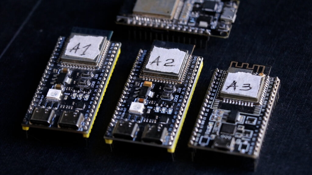
📍 Anchors (ESP32)
These are fixed nodes placed around the environment, and they constantly scan for the tag, measure RSSI, and send that data over Wi-Fi to a central server.
- Fixed positions
- Continuous scanning
- Real-time data transmission
🖥️ Server + Web Interface
On the backend, a Python server collects RSSI values from all anchors and processes them to estimate position, while a web interface visualizes everything in real time.
- Data collection
- Signal processing
- Live visualization
📐 Why Three Anchors?
To estimate a position in 2D space, you need at least three reference points, because each anchor gives you a rough distance estimate, and combining those estimates allows you to approximate where the tag is located.
- 1 anchor → no position
- 2 anchors → ambiguous
- 3 anchors → usable estimate
More anchors = better accuracy.
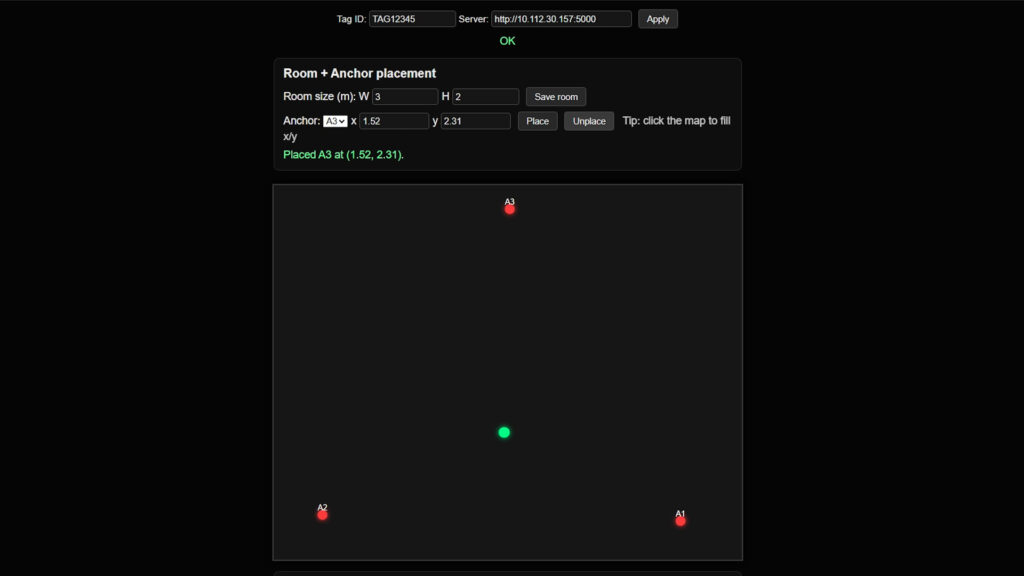
🧪 Testing — When It Starts Feeling Real
Once everything is configured, with all anchors connected to the same network and the server running, the system becomes interactive in a way that’s hard to appreciate until you see it working.
You place anchors on the map, define their positions, and after a few seconds:
A green dot appears.
Then you move the tag.
- The dot follows
- It jitters
- It corrects itself
Not perfect.
But alive.
⚠️ RSSI Reality — Noise Everywhere
This is where things get interesting, because RSSI is not a clean measurement, and the more you rely on it, the more you realize how unpredictable RF environments really are.
- Sudden jumps in position
- Drift when stationary
- Inconsistent readings
To reduce this, I added calibration:
- Measure known distances
- Capture multiple samples
- Fit a signal model
It helps.
But it doesn’t eliminate noise.
🤯 The Turning Point
At this stage, the system was working, but it still felt like a controlled demo rather than something dynamic, and that’s when a simple idea completely changed the direction of the project.
What if the thing I’m tracking isn’t in my hand… but moving on its own?
Something faster.
Less predictable.
So I decided to attach the tag to something mobile.
And that’s where things escalated.
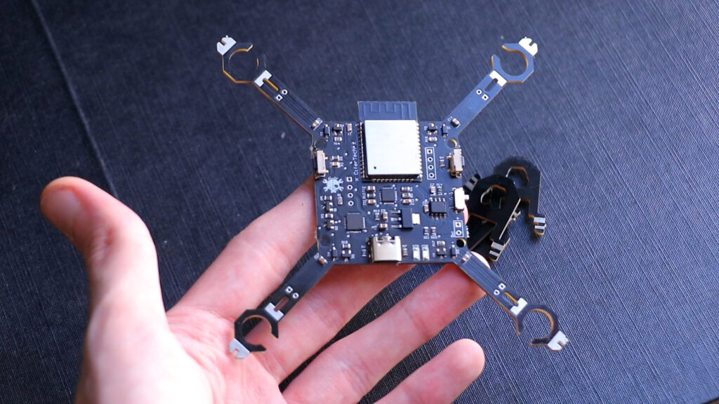
🔧 Hardware — Minimal Design, Real Constraints
ESP32 — Main Controller
- Control logic
- Communication
- Sensor processing
MPU6050 — Stabilization
- Gyroscope data
- Acceleration data
SI2302 MOSFETs — Motor Driving
- High current switching
- PWM control
Power System
- TP4056 → battery charging
- LF33 → voltage regulation
CP2102 — Communication
- Programming
- Debugging
🎮 Control System — From Pain to Usable
❌ Version 1 — Serial Control
Typing values to control motors. It worked… but it wasn’t usable....
Read more »