 electronicsworkshops
Introduction
The ESP8266 Programmer is a compact breakout board designed to simplify firmware uploading and serial communication for ESP8266 modules (such as ESP-01, ESP-12, etc.).
It integrates power regulation, USB-to-serial conversion, and automatic boot mode control into a single board. The inclusion of a USB-C connector ensures modern compatibility, improved durability, and reliable power/data transfer.
For Full Project:
https://electronicsworkshops.com/esp8266-programmer-board-usb-c-based/
Objectives
Provide a plug-and-play solution for ESP8266 programming
Eliminate the need for external FTDI modules and manual wiring
Ensure stable 3.3V power supply
Enable automatic flashing mode (no manual GPIO switching)
Use modern USB-C interface
Block diagram
The block diagram shows the overall flow of the system. Power and data enter through the USB-C connector, where the protection circuit (diode and fuse) ensures safe operation. The voltage regulator converts 5V to a stable 3.3V required by the ESP8266. Meanwhile, the CH340C converts USB data into UART signals for communication. The auto-program circuit, controlled by RTS and DTR signals, manages GPIO0 and RST pins to automatically switch the ESP8266 into programming mode. All blocks work together to provide a seamless programming interface.
Circuit Diagram Explanation
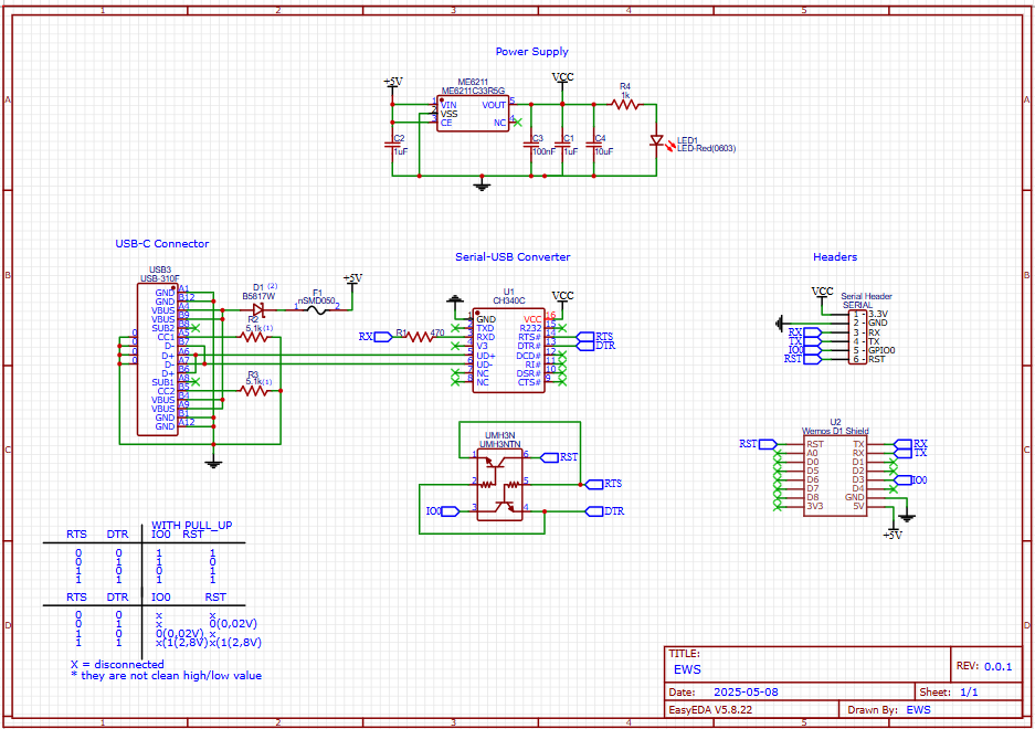
In the circuit diagram, the USB-C connector supplies 5V, which is protected using a Schottky diode and fuse before feeding the ME6211 LDO regulator to generate a stable 3.3V output. Capacitors are placed at input and output for filtering, and an LED indicates power status. The CH340C USB-to-serial converter connects to USB data lines (D+ and D−) and provides TX/RX communication to the ESP8266. The RTS and DTR pins from CH340C are routed through a dual NPN transistor (UMH3N), which automatically controls the ESP8266’s GPIO0 and RST pins for flashing. Finally, header pins expose power, serial, and control signals, allowing easy connection to ESP8266 modules like ESP-01 or D1 Mini.
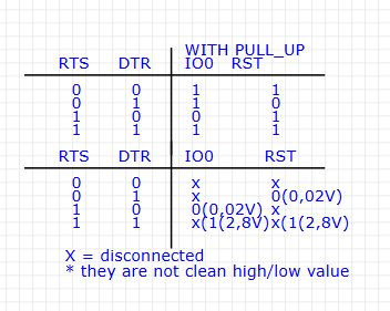
This table shows how RTS and DTR signals control GPIO0 (IO0) and RST for automatic programming of the ESP8266. With pull-up resistors, both IO0 and RST stay HIGH by default. When RTS/DTR change states, the transistor circuit pulls IO0 LOW and toggles RST to put the ESP8266 into flashing mode; otherwise, it stays in normal boot mode.
The second part shows real voltage behavior, where signals are not perfectly HIGH/LOW. Values like 0.02V (LOW) and 1.2–2.8V (uncertain) appear due to transistor switching. “X” means the pin is not actively driven. Despite this, the circuit works reliably for auto reset and programming.
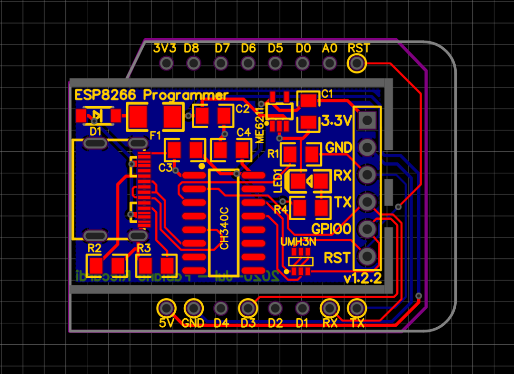
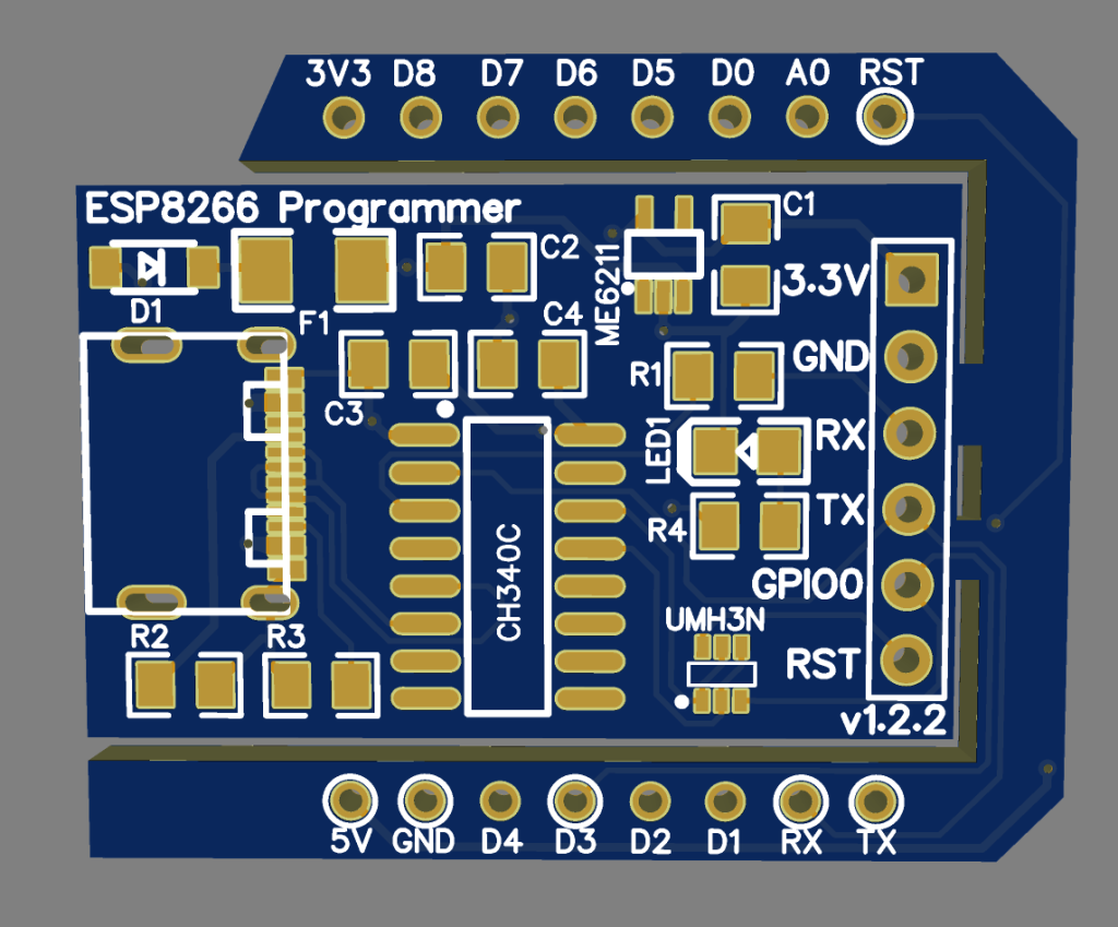
PCB Files
Order Directly from PCB WAY
I have already uploaded all these required manufacturing files in PCBWAY website. You can easily go to the below link and place you order, and get your Own Home Automation PCB manufactured from one of the best pcb manufacturer PCBWAY
Conclusion
The ESP8266 Programmer Board with USB-C is an efficient and modern solution for developers working with ESP8266 modules. By combining power regulation, USB-to-serial conversion, and automatic boot control into a single compact board, it significantly simplifies firmware uploading and debugging.
This design improves reliability, reduces wiring complexity, and enhances user experience—making it ideal for both beginners and professionals in embedded systems and IoT development.
For Full Project:
https://electronicsworkshops.com/esp8266-programmer-board-usb-c-based/