In memory of the "Point de vue du Gras".
In typical consumer cameras, each pixel of the photograph uses three such elements, each with a colour filter that restricts light detection to a narrow spectral band (red, green, blue).
But what if we use only one light‑sensitive element (a future single pixel) and obtain a photograph by moving this element along two axes while recording the brightness value at each point of the future image? Effectively, this would be a primitive scanner. We just need to project the future photograph onto a virtual plane (as in a conventional camera).
Photoresistor.
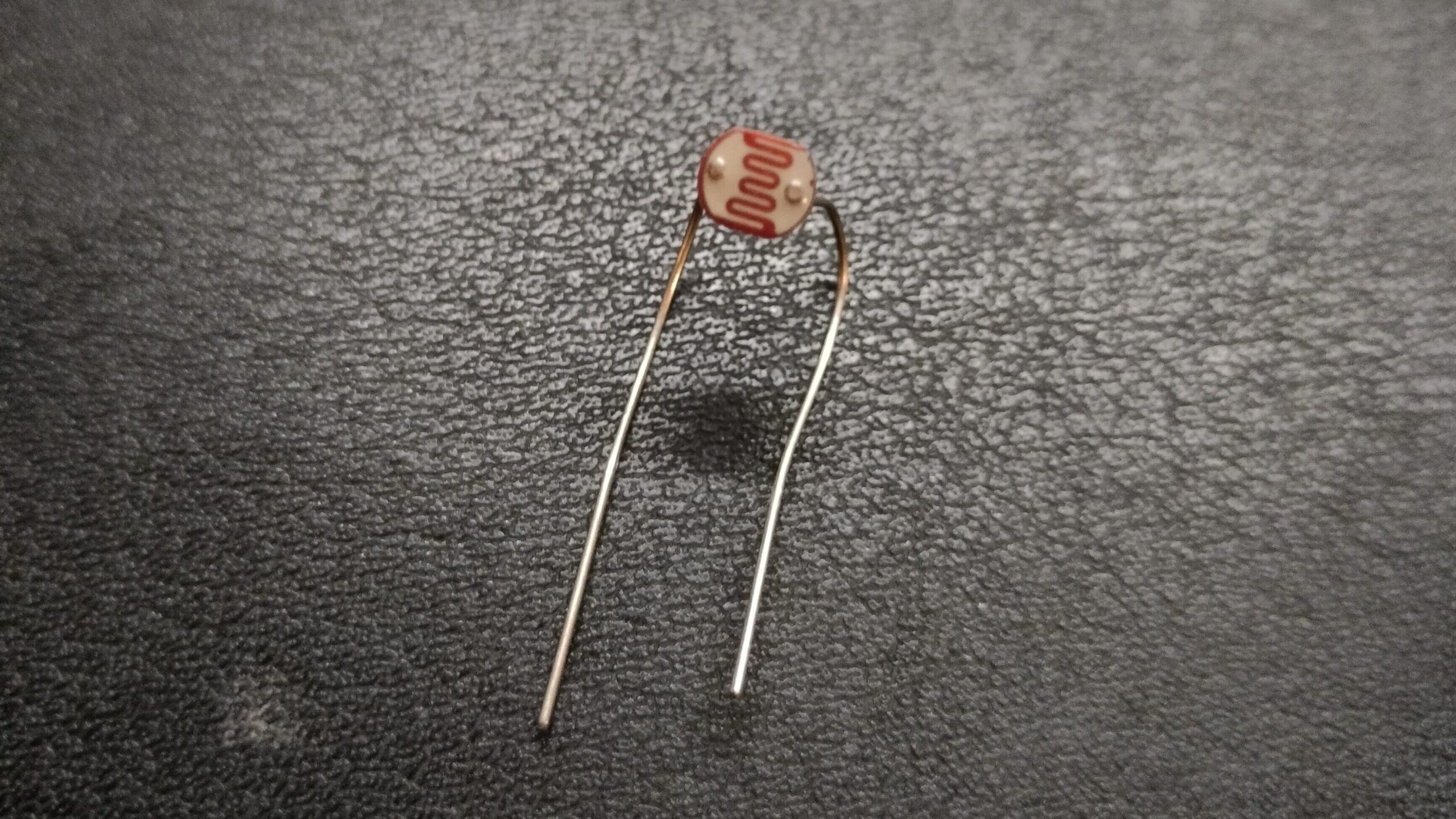
As the sensing element one can use a photoresistor. For movement, two stepper motors and leadscrew‑nut transmissions can be employed, similar to CNC coordinate machines.
The size of a photoresistor is about 5 mm, meaning the physical pixel size is 5 mm. For a 320×200 pixel photograph, the distance the photoresistor would have to travel is about 1.6 metres along the longer side.
If we aim for an exposure time (i.e., the time to produce one photograph) of at least 20 seconds, we would need a speed of 3200 pixels per second, i.e. 10 lines per second.
Clearly, implementing such a design in a DIY format is hardly achievable — moving a carriage with a photoresistor 20 times (including return travel) over 1.5 metres in one second is beyond reasonable capabilities.
Therefore we must keep in mind that shooting this way is a very slow process. Possibly even a bit romantic, harking back to the era of analogue photography when shooting also took quite a long time (though for different reasons).
To reduce the shooting time, one can apply a mask to the photoresistor — to reduce the physical size of the sensing element and thus decrease the step of the physical grid used for light registration.
Mechanics and electronics
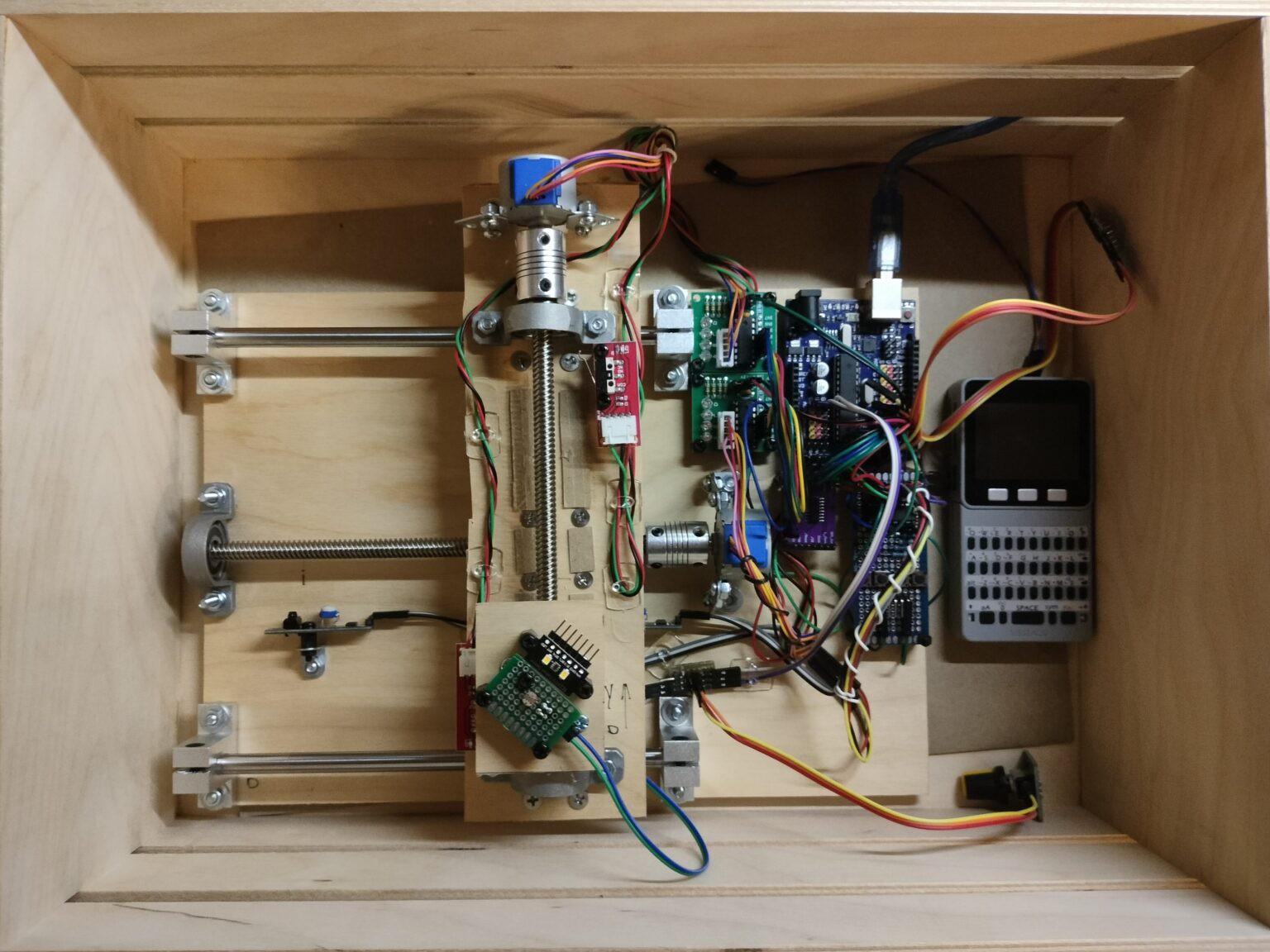
To control the photoresistor carriage I used two stepper motors (28BYJ-48-5V) with included drivers, and off‑the‑shelf leadscrew‑nut actuators. These are easily found on AliExpress or in local shops selling Arduinos and various accessories.
Control is done with an Arduino Uno. The motor drivers are connected via a 74HC595N shift register to reduce the number of used outputs.
Data from limit switches (to know when to stop the motors) and a manual control button (for debugging) are read using a 74HC165N shift register — again to reduce the number of connections to the Arduino. As limit switches I used whatever was in stock: for one axis, IR sensors with digital (logic) output; for the other axis, ordinary push‑button switches with digital (logic) output.
To measure luminous flux, a simple circuit is assembled: connect the +5V from the Arduino to one pin of the photoresistor, and the other pin to the Arduino's analog input. A variable trimpot is connected in parallel with the photoresistor to adjust the input voltage so that the digital values at the analog input pin do not fluctuate between 1024 and 0 in bright or low light conditions. This effectively measures the voltage drop across the 5V pin.
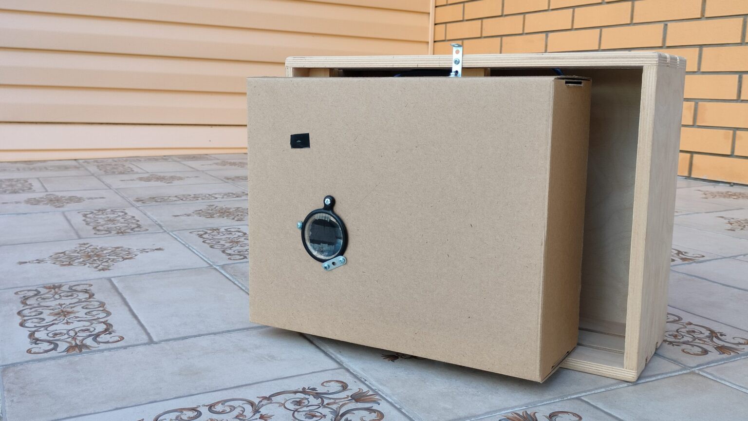
The entire assembly is mounted on plywood in a wooden crate.
Render picture and some improvement
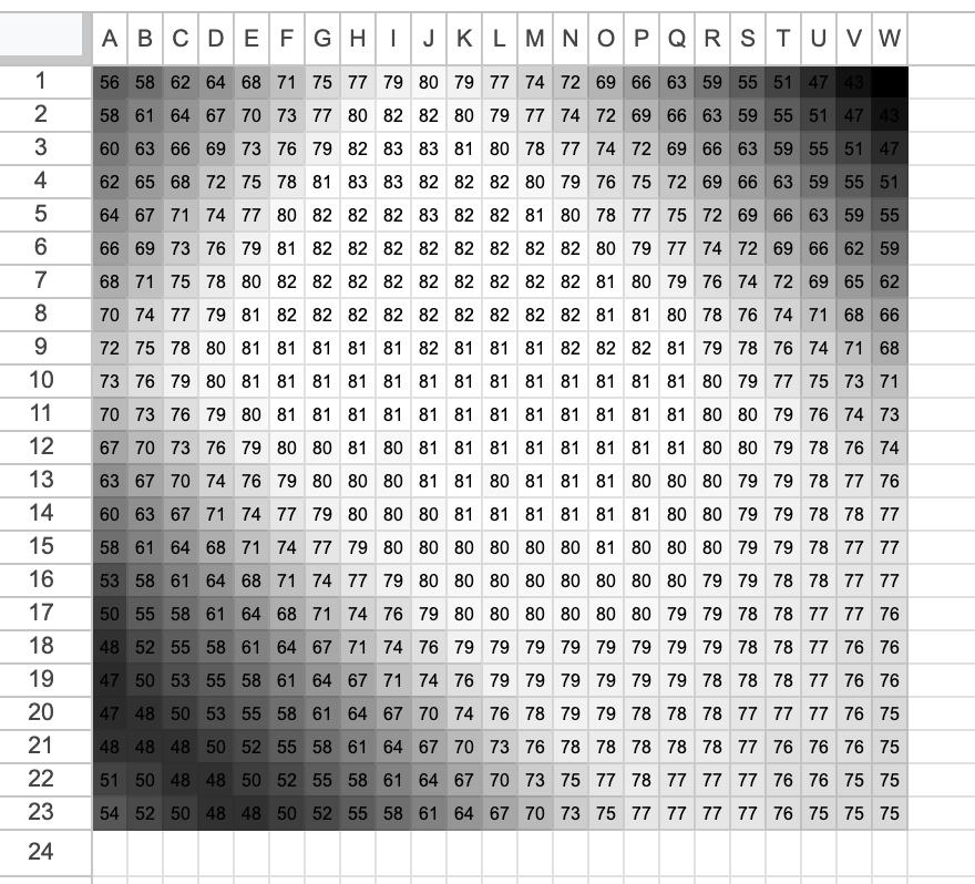
The data from the photoresistor, output to the monitor port, is then manually transferred to a Google spreadsheet. The cells are then colored using conditional formatting with a gradient. The minimum value in all cells is black, and the maximum value is white.
Because the integral sensitivity (i.e., the dependence of voltage on the drooping conversion) is close to linear, this approach allows small-range measurements to extend the entire grayscale range on the computer screen. In simple terms, the range of readings on the standard input, for example, from 46 to 81, is converted to a range from 0 to 255 (grayscale levels) or any other value; to achieve this, a contrast result must be obtained.
Tests
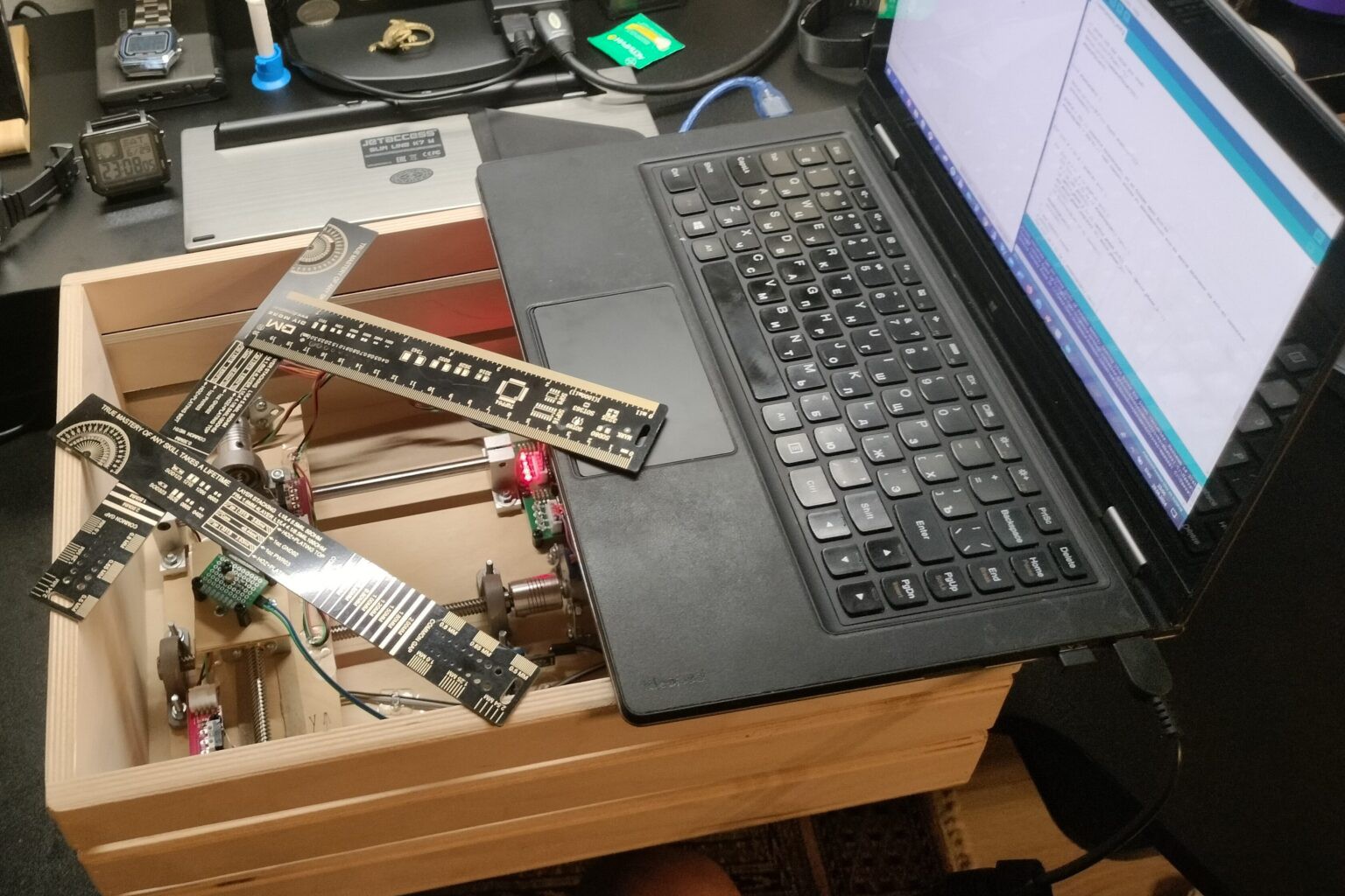
The initial tests on a small number of points demonstrate the correct operation of the circuit and the potential of the assembled design. One of the tests looked like this: in front of the plane of motion, the photoresistor bounded three lines, which cast a shadow from the lamp above the table. The photoresistor readings are recorded in increments of approximately 5 millimeters, i.e., 1 pixel of the resulting image is designated as 1 measurement on a 23x23 grid with a 5 mm grid pitch.
Speaking of photoresistor voltage measurements, experiments showed that either due to lamp flickering or external low-voltage sources, the readings were extremely unstable. Therefore, a function was written into the code that took multiple readings at a time, taking multiple levels and recording the average value. This simple trick allows for almost complete stabilization.
To confirm the design's ability to capture images with at least a reasonable resolution, a sheet of paper with a black-and-white image was used, which was shined through by a lamp.
To ensure that the focal plane coincided with the plane of the photoresistor's movement without the use of any lenses, the image was positioned almost flush with the plane of the photoresistor's movement. This also eliminated the influence of external light on the photoresistor.
The result is inspiring!
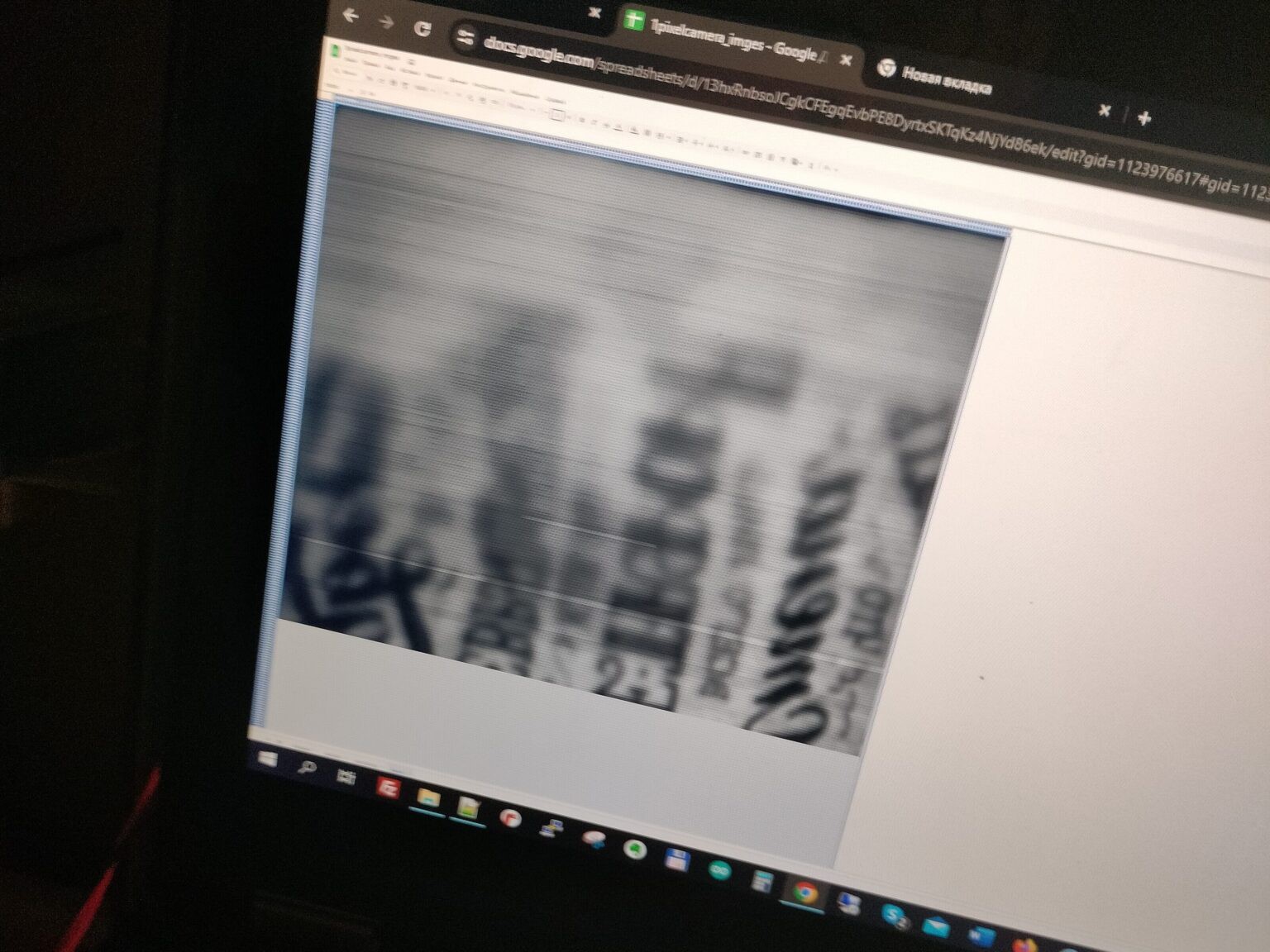
Firstly, the image size is 221 x 186 pixels—enough to accommodate discernible objects. Incidentally, the physical size of the scanned field is 11 x 9 cm.
Secondly, obvious design nuances immediately became apparent: high sensitivity to changes in the external or internal environment, as well as to misalignment of the focal plane with the actual plane of movement of the photoresistor.
The visible horizontal stripes are the effect of changes in the recording time:
- the ambient illumination (I observed the process, and my shadow sometimes fell on the setup, sometimes not),
- the current source that acts as the carrier signal.
The significant blurriness in the upper part of the resulting image is due to the fact that the shaft along which the carriage moves does not have a straight axis, but is slightly curved. Or, more likely, the thinness of the paper caused one part of the sheet to sag more, closer to the photoresistor. This means the sheet of paper wasn't actually flat, but had a slight curve from one edge to the other.
In any case, the resulting image clearly showed that everything was working.
Lens
The next step was to make something resembling a lens. A simple pinhole camera would be an option, but the pinhole seemed too small to let in enough light, so I bought the cheapest magnifying glass (I think it was 2x) and used it as a lens. A cardboard box served as the lens's "body." Through experimentation, I determined the approximate focal length for shooting the landscape (the house across the street).
The most difficult part turned out to be creating a design from available materials that would allow the image to be projected onto the desired plane of movement of the photoresistor.
Final result
After about a whole day of exposure, which is about 8 hours, the result was obtained
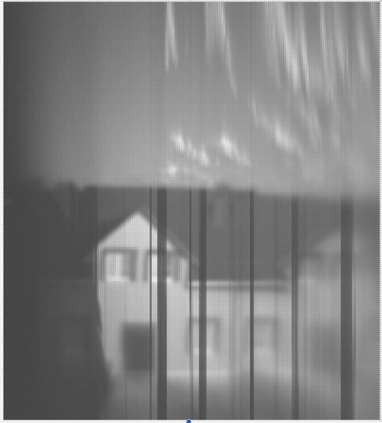
The top section shows the sky with clouds. Because the clouds are moving, they are not captured in a single instant, as in a normal photograph, which gives them their strange appearance.
The dark streaks indicate that the sun was obscured by a cloud at these moments, meaning the light flux is significantly lower than in direct sunlight. The problem of dark streaks can be solved by adding a +1 photoresistor to the camera, which will record changes in the overall illumination. Then, taking both readings into account, a more even image should be obtained.
Stronger blurriness on one side indicates either a non-parallelism between the focal plane of the lens and the plane of motion of the photoresistor. Alternatively, it could be the result of a small lens focal spot, with the center of focus of the lens circle not being in the center of the scanning field, resulting in blurriness in only one part of the photograph.