The circuit works as follows. Q101 is a power PFET that functions as a pass element between the battery pack and drill / charging port. It is normally on and allows current to flow to the drill or into the pack. U101 is a high voltage push-pull comparator with the inverting input connected to the precision 5V reference provided by U102. U101 compares the input voltage sensed by the divider R102/103, and when it exceeds the reference value its output swings high and turns off Q101. Q101 will remain off as long as the charger is connected. When disconnected, Q101's body diode will conduct, power-up the protection circuit, and turn Q101 back on. Q101's G-S limit is 20V so no protection is necessary.
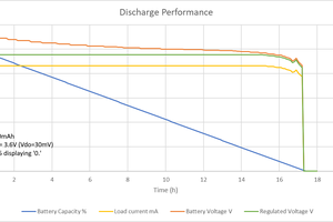
A drawback to this solution is that it draws about 3mA continuously so it will discharge the pack over time. In this setup, it will take about a month to lose 50% from a full charge. This isn't a problem if the tool sees regular use, but if it sits on a shelf for extended periods it must be periodically charged to avoid permanent battery damage. A simple solution would be to add a switch, but with a tool it can be challenging to place somewhere ergonomic yet durable (not to mention installation).
I was able to use the original pack housing for my replacement LFP batteries and had sufficient room for the protection circuit. I didn't bother to make a PCB; rather it is fashioned from hacked sections of PCBs for other designs. If you build this, pay attention to the operating voltage & peak [operating] current of the tool. Most MOS-FETs (P & N) are limited to 20V G-S, so gate protection may need to be added . Also confirm that the FET will handle the peak & continuous current demanded by the tool, and based on the tool's duty cycle that the FET has adequate thermal margin.
 George
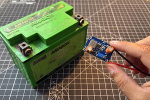
 Sagar 001
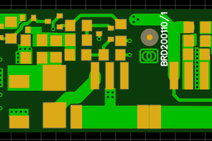
 Christoph Tack