 Jesse Farrell
I've recently been exploring all kinds of home automation tools with Home Assistant. If you're not familiar, Home Assistant ties together various smart devices into a single system and gives the user (what seems like) infinite control. I'd highly recommend it to nearly any engineer type.
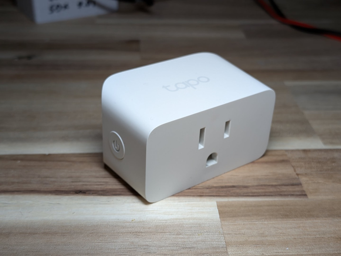
Anyhow, I bought myself a few Tapo p110m smart plugs. These allow me to turn off lamps across the house and automate simple scenes. Unlike many other smart plugs on the market, the p110m includes energy monitoring. Home Assistant goes a little further and exposes voltage and current for us to play with.... And play we shall!
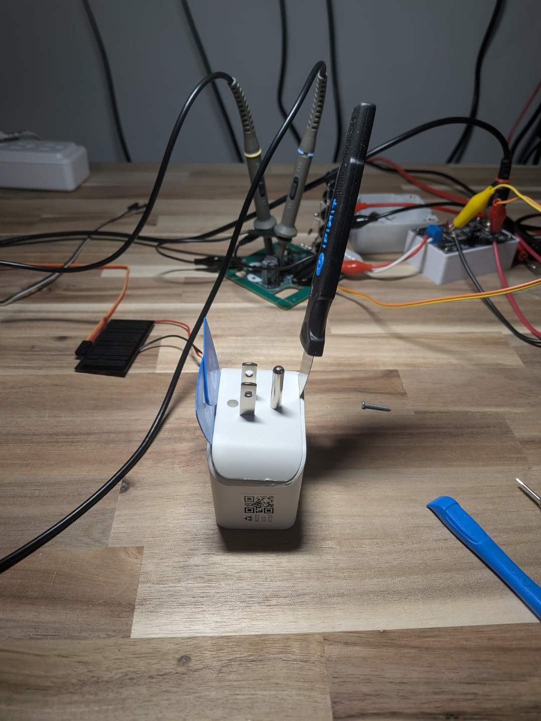
First things first, we need to tear the product down to understand how it works. I might have to "fake" some of this test depending on how the harware is wired. Tearing these things apart was not elegant or fun.
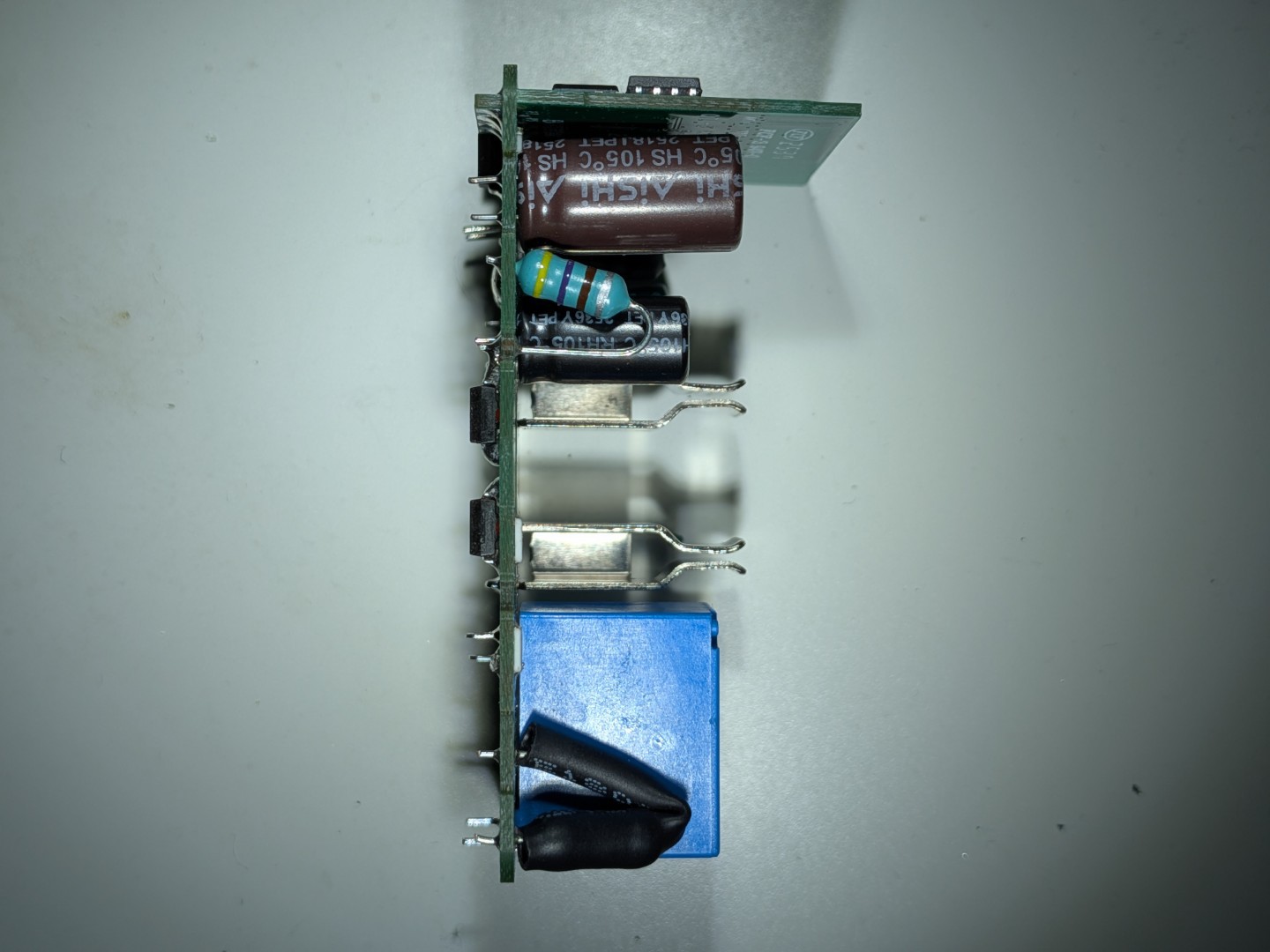
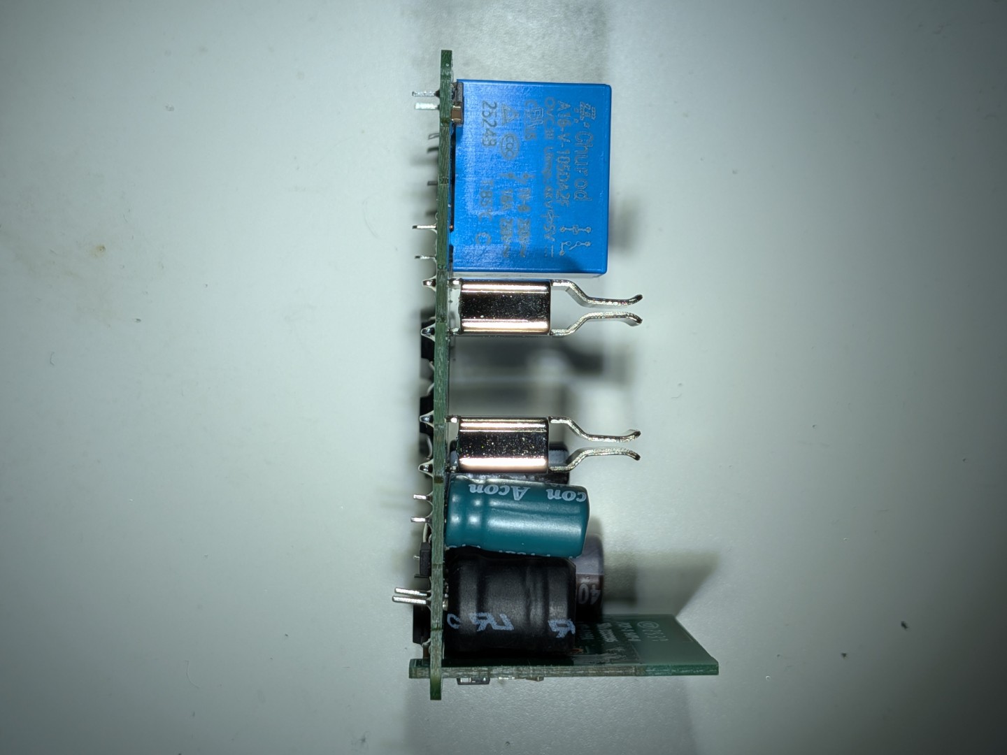
Once free of it's plastic cage, I had to desolder two pins connecting the PCB to the hot and neutral spades. Afterwards the board looked as shown below.
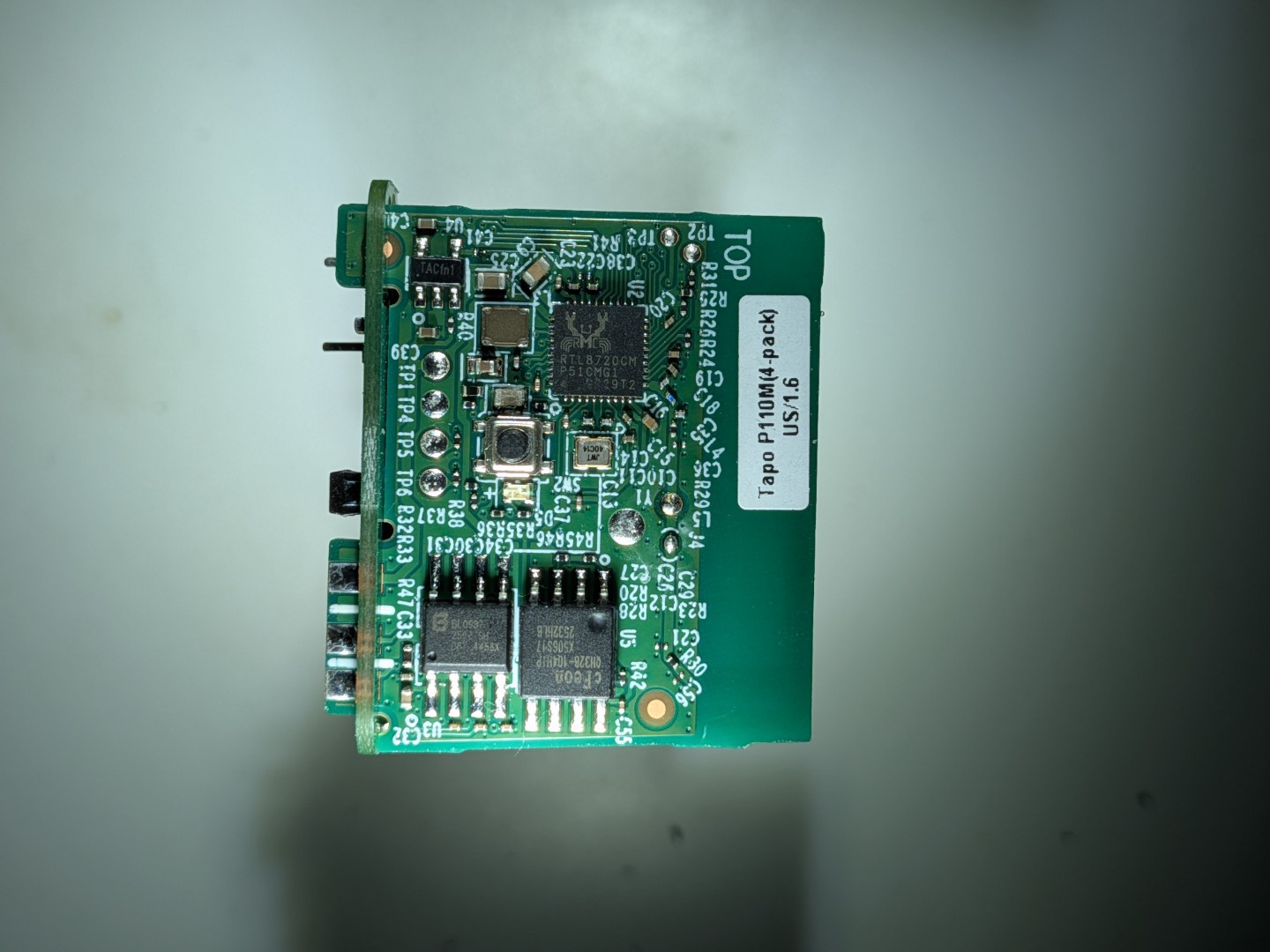
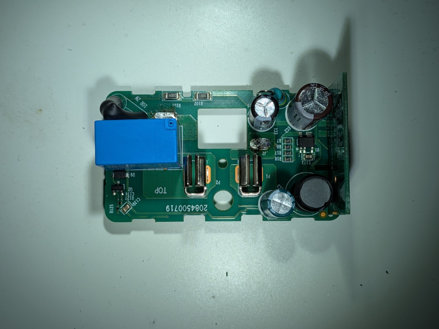
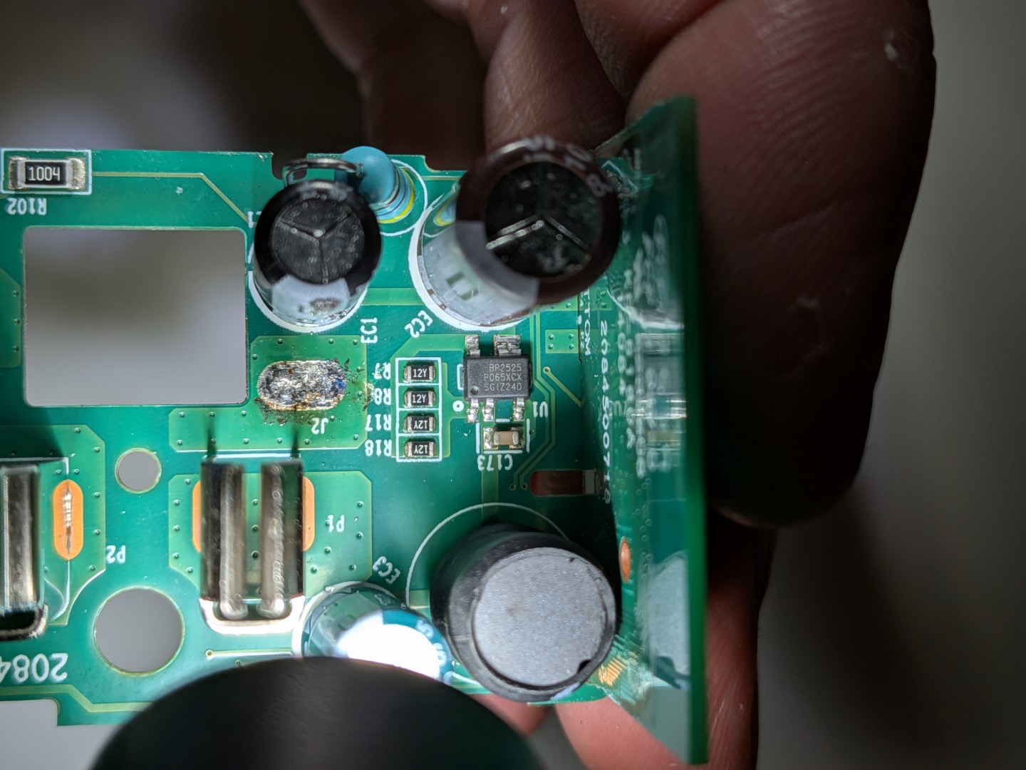
Some key parts I found for those playing along at home...
- Energy Monitor - Belling, BL0937
- Description: "Single Phase Energy Meter IC with Integrated Oscillator for Socket"
- AC/DC Converter - Bright Power Semiconductor, BP2525
- Description: "Low Standby Power Non-isolated CV Converter"
- Brains - Realtek, RTL8720CM
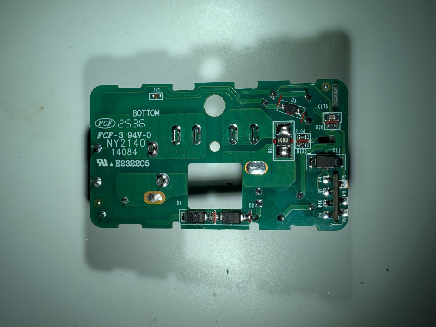
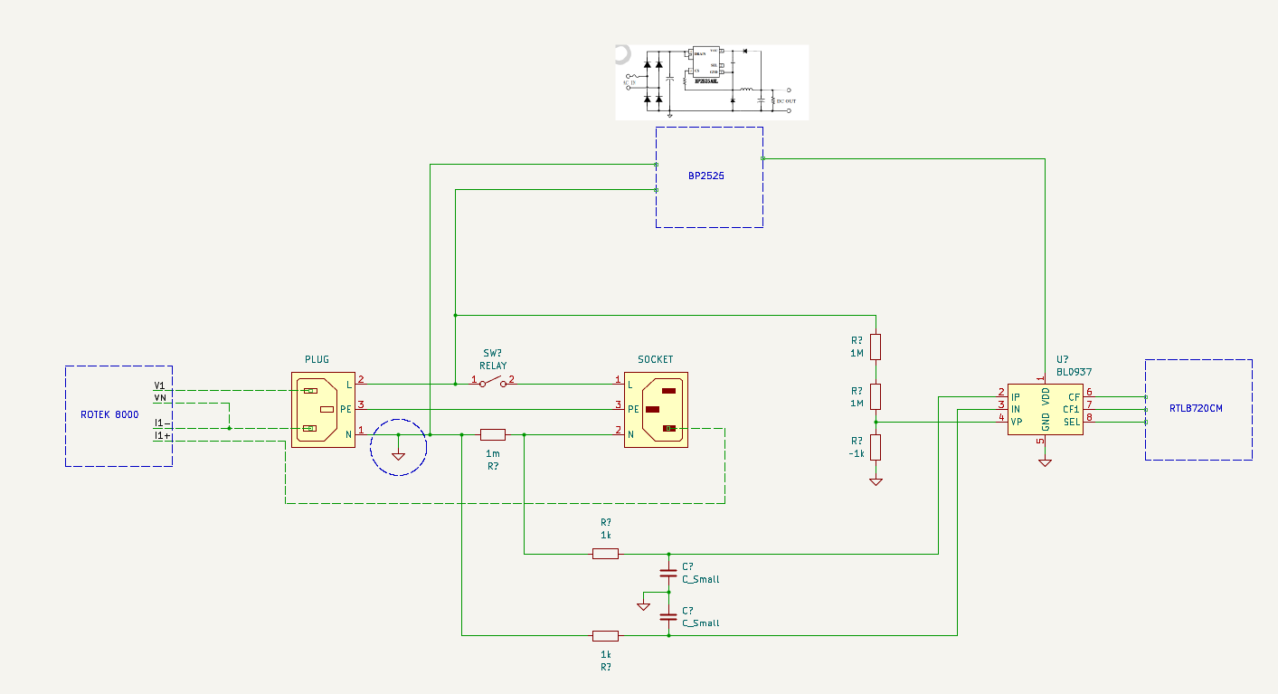
The engineer who designed this circuit decided to measure the current on the neutral wire (return current) and not the hot wire (sending current). This simplifiies my test setup alot. If they were measuring current on the hot side, I'd have to either inject a common mode voltage ontop of my current source (which I'm not particulalry willing to do), or I'd need to start modding this PCBA to seperate the voltage from the current measurment.
I sketched out a rough schematic for my test setup, including the critical parts of the p110m circuit. Essentially, I plan to energize Line and Neutral using my Rotek 8000 AC calibrator, then I will connect I1+ to the user facing Neutral socket of the p110m, and I1- can be shorted to VN on the calibrator.
Revisting w/ Results
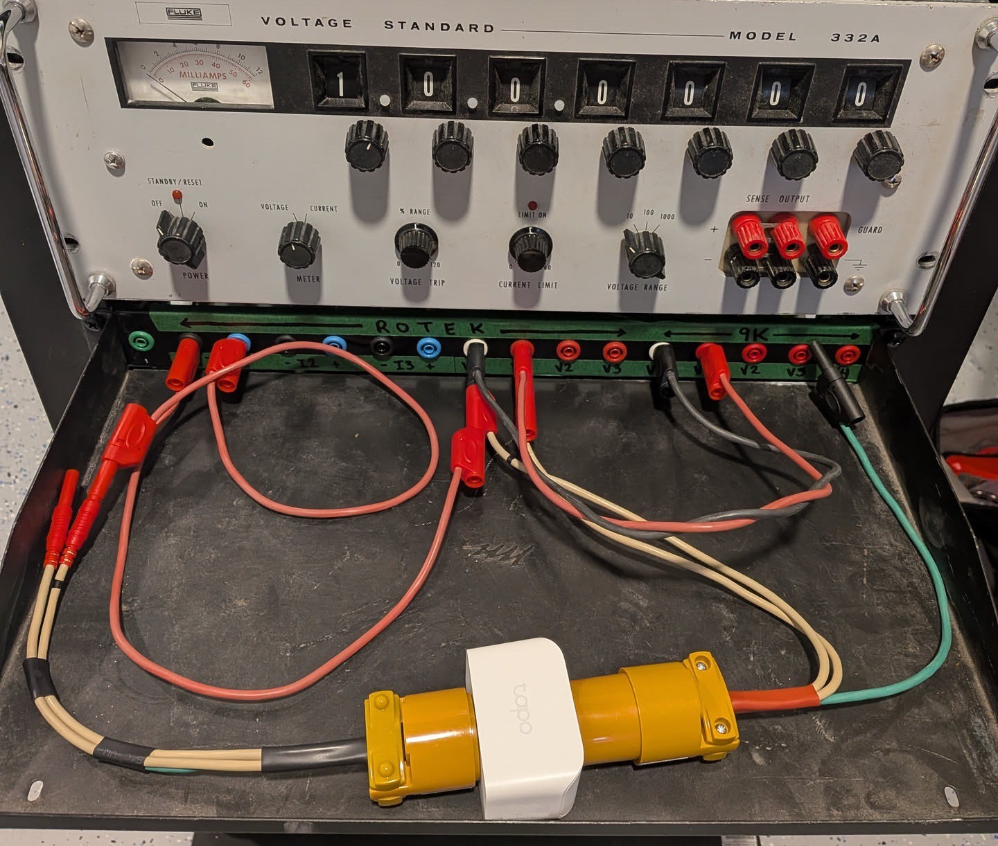
I rewired my power rack, and finished a different project since last I posted here.... finally got around to dumping the data!!!
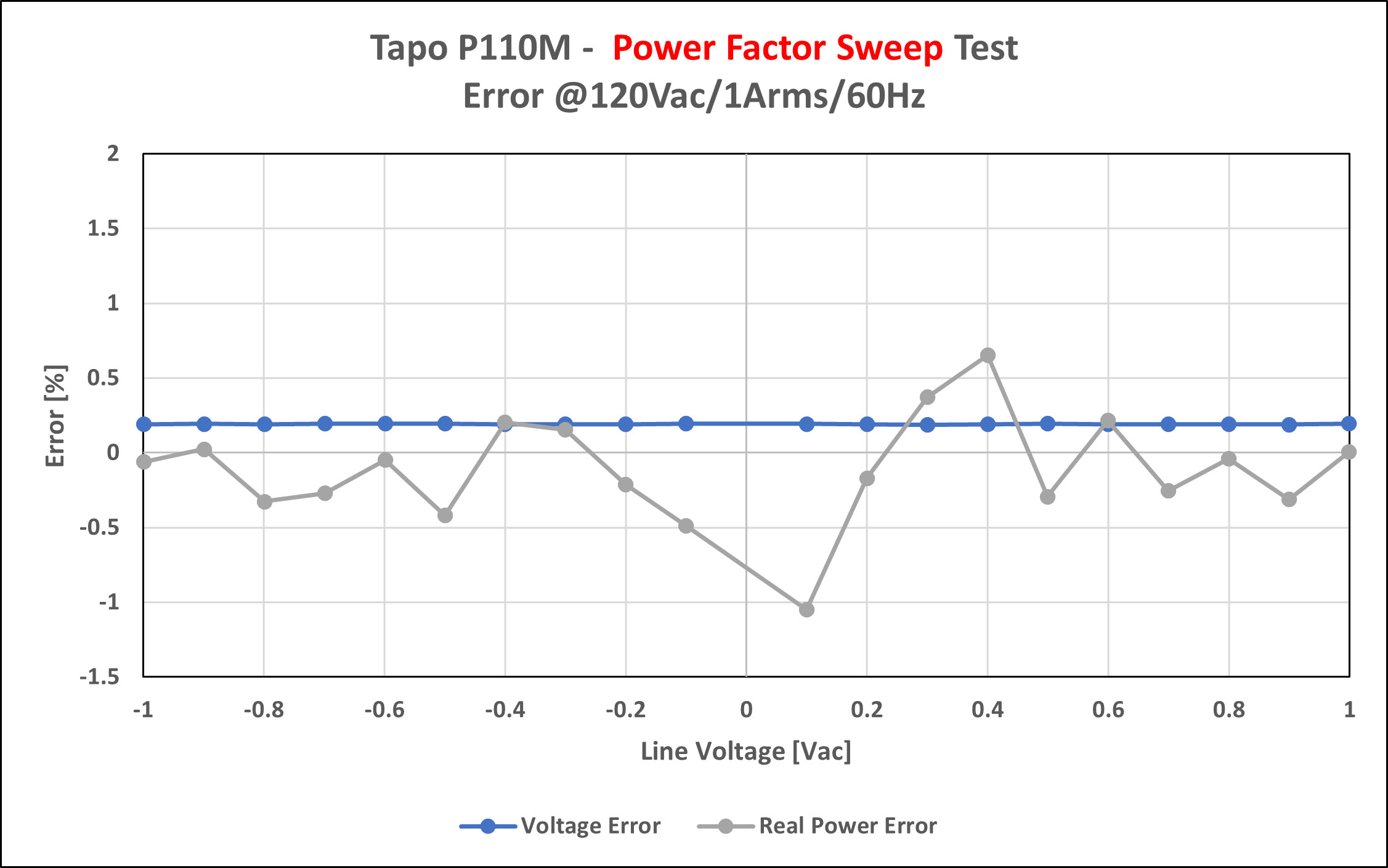
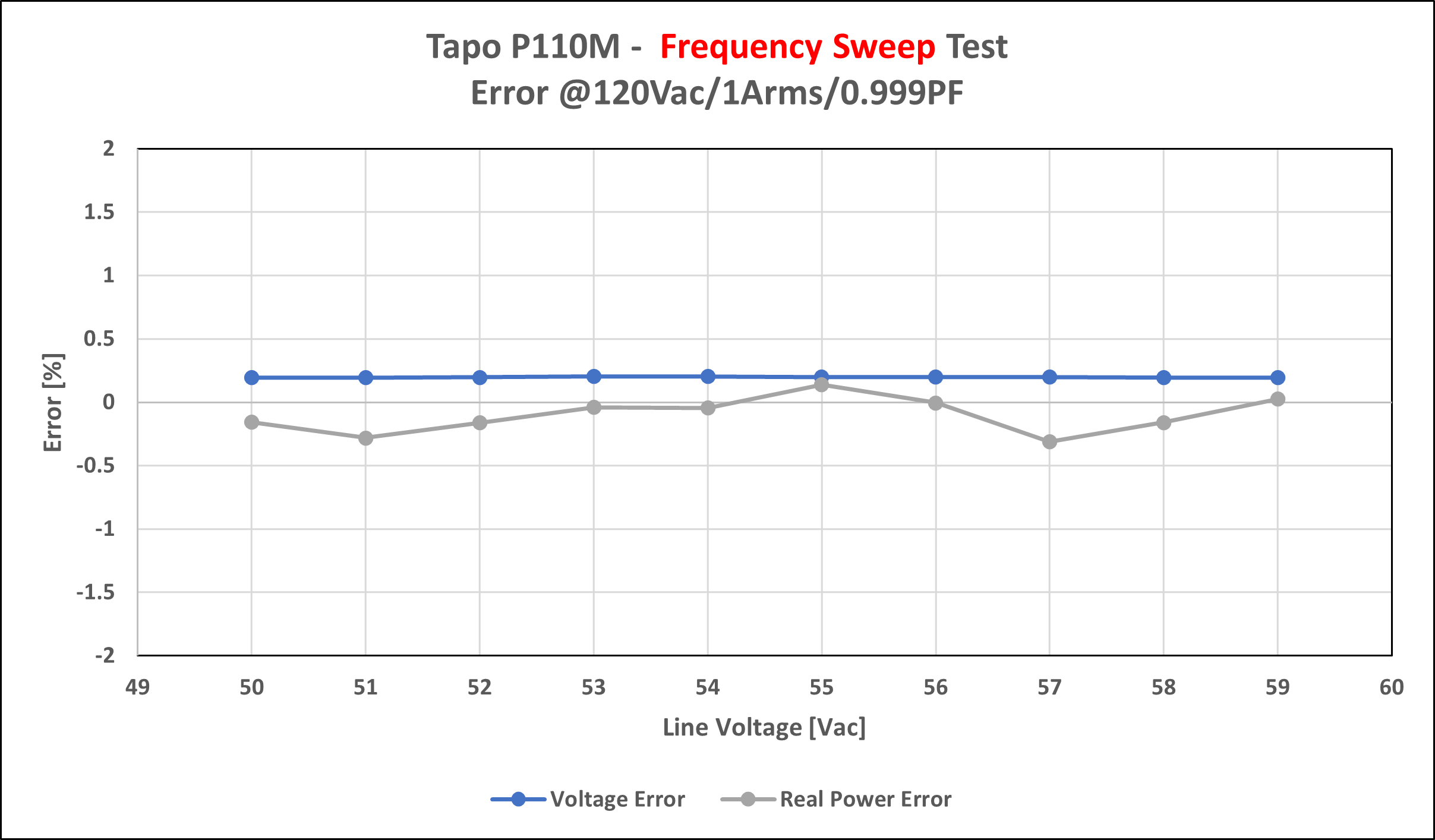
For this accuracy test I’m using a Rotek 8000 as the source, and an ION9000 as a reference. I’m sweeping current, voltage, power factor and frequency. 0.01-15A @120Vac/0.999PF, 90-240Vac @1Arms/0.999PF, -0.999-0.999 PF @120Vac/1Arms and 50-60Hz. The update rate of the p100m isn’t clearly listed anywhere, but I found waiting 15 seconds gave the system time to sync up to the test signal (I suspect there’s some aggressive averaging going on). I then sampled each datapoint 3 times to give it some amount of statistical relevance.
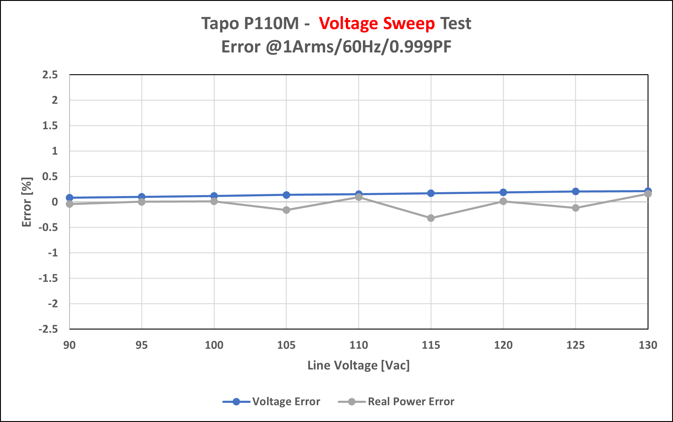
Across all sweeps the power and voltage accuracy remained “accurate” relatively speaking for a product that makes no accuracy claims. The system is pretty unaffected by changes to line voltage, power factor and frequency. Voltage error remained below 0.5% throughout the tests, and power error peaked at 10% at low current (10mA).
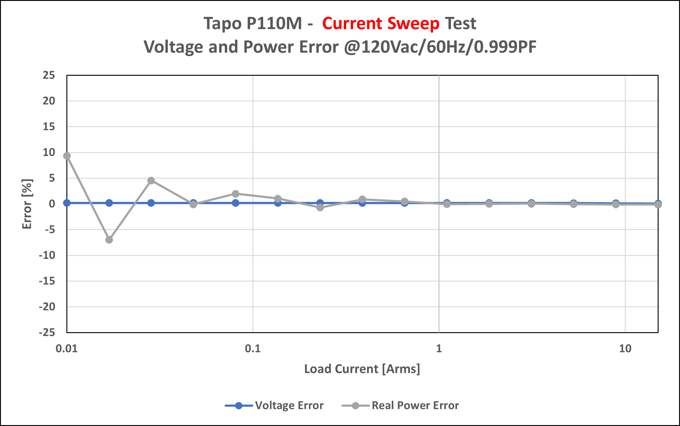
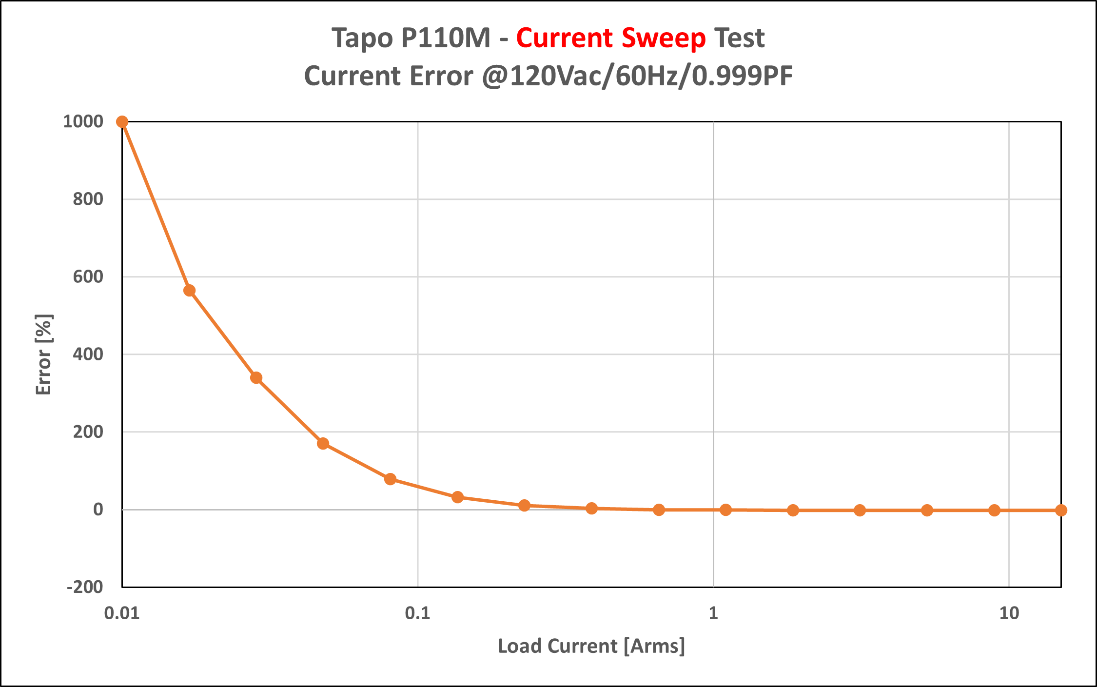
The current error on the other hand is pretty awful. It seems like the P110M is reporting uncalibrated current readings. As a result, the current error is 1000% at 10mA, and ~50% error at 100mA. Yet there must be some sort of calibration going on, otherwise the kW readings would be similarly terrible.
Looking at the raw readings, tells a similar story. The P110M clearly struggles at the low end, but it's kW readings are relatively unaffected.
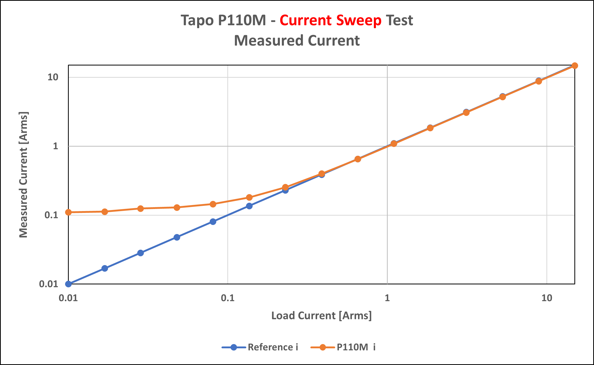
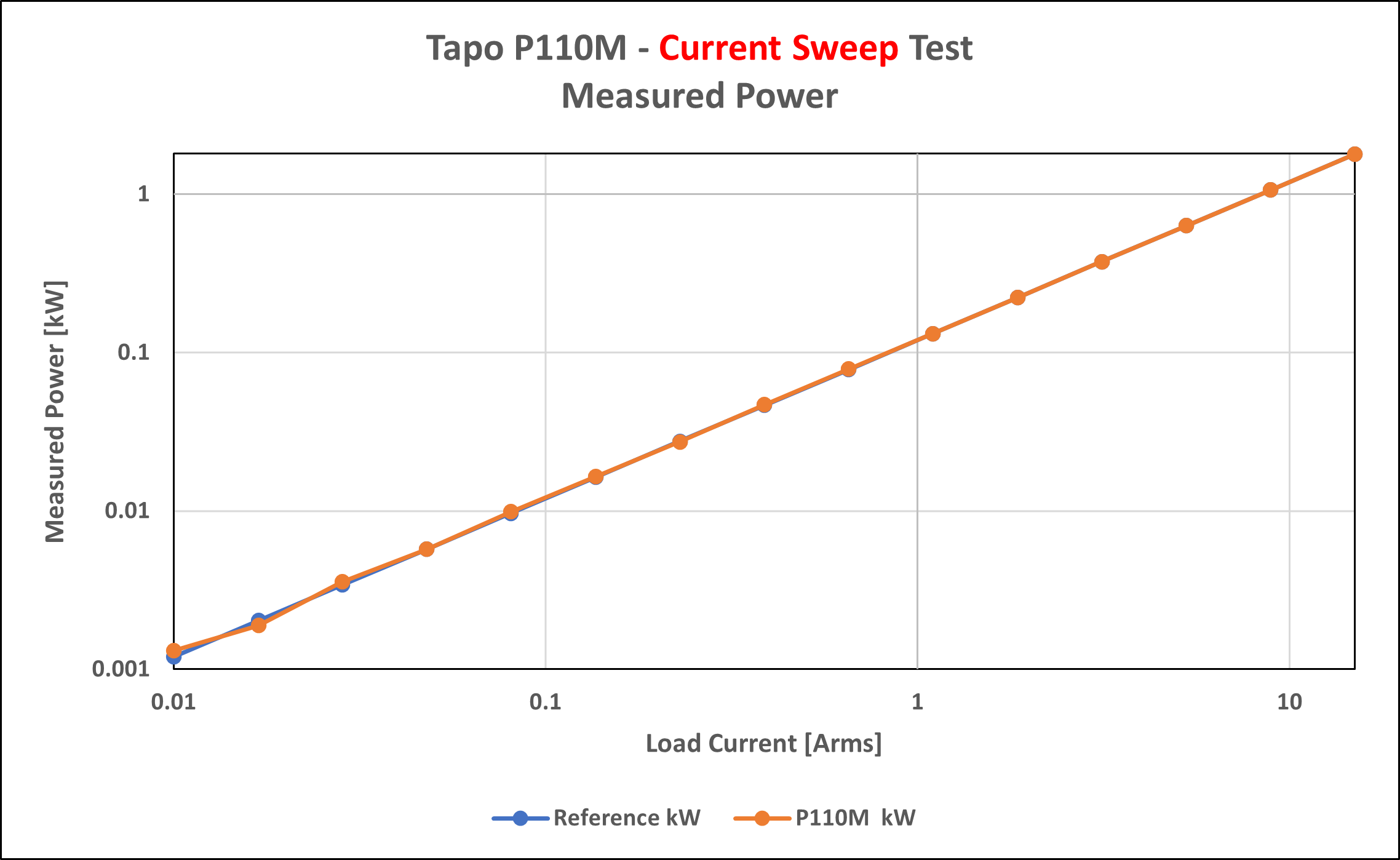
We could derive the current from the more accurate power measurement, but the device sadly doesn’t report any PF data. In summary then, don’t trust the P110M’s current reading below ~1A. Ignoring the uncalibrated current readings, the device is generally within 1-2% error above 100mA.
If you’re interested in the data, I uploaded the excel file to this project page.
Discussions
Become a Hackaday.io Member
Create an account to leave a comment. Already have an account? Log In.