 namnam
The Problem: The "Industrial Gap" in LoRa Development
Most LoRa development boards on the market fall into two categories: simple breakout boards for hobbyists or expensive, closed-source industrial gateways. For developers trying to build professional sensor nodes, this creates a major hurdle.
Real-world industrial sensors (pressure, flow, temperature, air quality) almost always communicate via RS485 (Modbus RTU) or 0-10V Analog signals. Standard LoRa boards require messy wiring, external level shifters, and custom power management to work with these sensors, making the final product bulky and unreliable.
The Solution: ArduLora
ArduLora was designed specifically to bridge this gap. It is an "All-in-One" industrial LoRa node that combines a powerful LoRaWAN module with the essential interfaces needed in the field.
By integrating the RAK3172 (STM32WLE5CC) with a high-performance RS485 transceiver and high-resolution analog inputs, ArduLora allows you to go from a prototype to a deployed industrial sensor node in minutes, not weeks.
Technical Deep Dive
- Module: RAKwireless RAK3172. This module is the heart of the board, running the RUI3 (RAKwireless Unified Interface V3). This allows developers to use the same C++/Arduino code for both LoRa P2P and LoRaWAN applications.
- Industrial Connectivity:
- RS485 (Modbus RTU): Integrated transceiver connected to Serial1. This enables communication with thousands of existing industrial sensors.
- Dual Analog Inputs: Two dedicated pins (AI1/AI2) configured for a 0-10V range. This is standard for PLC and industrial sensor outputs.
- Smart Power Management:
- The board features a dedicated control pin (
PB5) to power up/down external sensors. This is crucial for battery-powered nodes where you only want to power the sensor for a few milliseconds during a measurement. - Deep sleep support with micro-amp current consumption.
- The board features a dedicated control pin (
- User Interface: Three status LEDs (PA8, PA9, PB2) provide instant visual feedback for transmission, reception, and system status.
Why ArduLora?
What makes ArduLora unique is its Native Arduino Compatibility. Unlike many industrial boards that require complex IDEs or custom SDKs, ArduLora works directly with the Arduino IDE. We've even published an official ArduLora Library to simplify sensor reading and data transmission, making professional IoT development accessible to everyone.

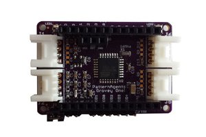
 Pattern Agents
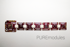
 Pure Engineering
 James Cannan
 Maker-fabs-J
🛒 Where to buy
https://www.tindie.com/stores/thanhnamlt5
https://www.elecrow.com/ardulora.html