Close
0%
0%

Building a Real-World SDR

Bridge the gap between SDR experiments and real wireless prototypes, enabling new PHY algorithms to be tested in a working RF system.

Similar projects worth following
Software-defined radio has fundamentally changed how wireless systems are researched and developed. My team has extensively used commercial SDR platforms for wireless research and algorithm development. But as our work moved from signal-level experiments toward complete wireless communication systems, our needs began to change.

We needed more than an SDR for observing and processing signals. We needed a platform where we could actually build a wireless communication prototype.

So we built Integrive-100.

Notes from our journey building a real-world SDR platform.
Why We Built Integrive-100: From SDR Experiments to Real Wireless Prototypes

Software-defined radio has fundamentally changed the way wireless systems are researched and developed. With an SDR platform, engineers can generate and receive RF signals, experiment with new waveforms, evaluate modulation schemes, and validate communication algorithms without building custom radio hardware from scratch.

We followed the same path.

We have used commercially available SDR platforms extensively for wireless communication research and algorithm development. They are excellent tools for learning, experimentation, and rapid proof-of-concept development.

But as our work progressed from signal experiments toward complete wireless communication systems, our requirements began to change.

We needed more than an SDR for observing and processing signals.

We needed a platform on which we could actually build a wireless communication prototype.
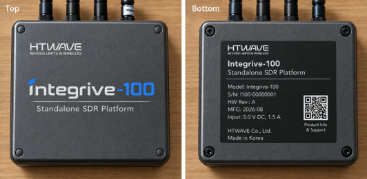
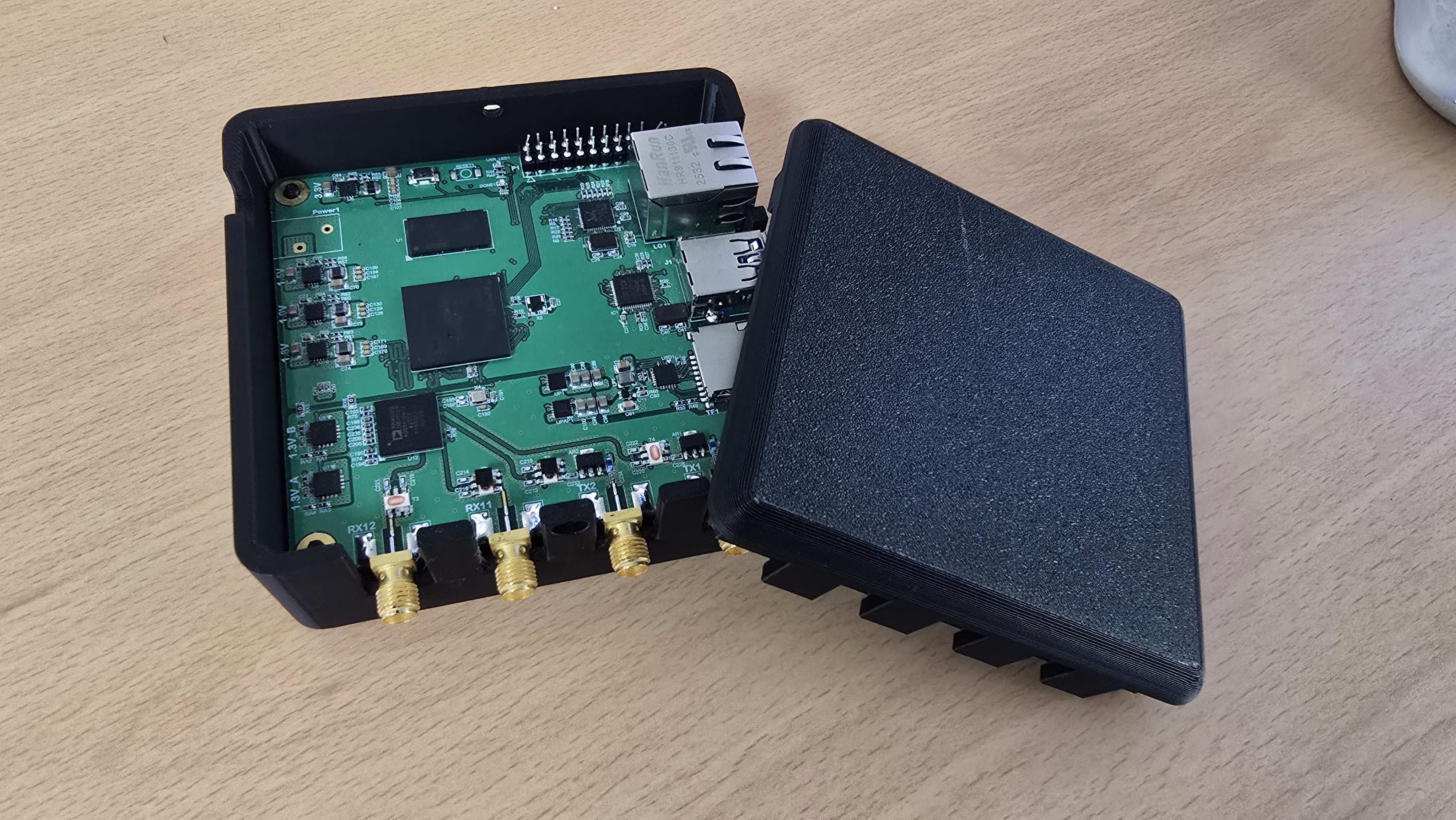
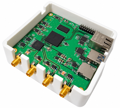
Figure 1. Integrive-100, the SDR development platform we built during this project.

The Gap Between an SDR Experiment and a Wireless System

A laboratory SDR experiment and a practical wireless communication system may use many of the same signal-processing algorithms, but they are not quite the same engineering problem.

In simulation environments such as MATLAB or Python, researchers can focus primarily on the algorithm itself. Many real-world effects can be simplified, modeled separately, or temporarily excluded.

Once an algorithm moves onto real RF hardware, however, phase noise, carrier frequency offset, I/Q imbalance, fixed-point effects, timing, interfaces, and hardware constraints all become part of the system.

Sometimes the challenge is not the algorithm itself. It is everything around it.

A new synchronization, channel-estimation, or equalization algorithm, for example, may assume a particular frame structure, pilot configuration, or position in the processing chain. If the development platform does not provide sufficient control over those elements, engineers may end up spending more time adapting their algorithms to the platform than evaluating the ideas themselves.

We wanted to reduce that friction.

A real communication prototype requires the entire signal chain to operate together, including RF processing, digital signal processing, synchronization, OFDM, modulation and demodulation, FEC, framing, packet processing, and communication protocols.

But we kept coming back to this question:

Why should we have to redesign the entire PHY just to test a new algorithm?

This frustration became one of the key ideas behind Integrive-100.

How We Structured the PHY

We wanted the PHY processing chain to be accessible enough that developers could focus on the particular function they wanted to investigate without having to build an entire communication system from scratch.

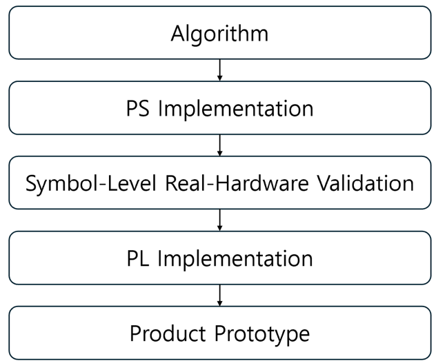
Integrive-100 provides an FPGA-based PHY implementation in the Programmable Logic (PL), together with an ARM-based Processing System (PS) running Linux. During algorithm development, a selected PHY function can be implemented in software on the PS, while the remaining PHY functions continue to execute in the PL.

This creates a practical development model:

Develop the PHY function you want to investigate in the PS. Let the existing PL implementation handle the rest of the communication chain.

What makes this particularly useful is that the algorithm can be evaluated as part of an operating PHY chain rather than only against previously captured data. PHY processing can be handled at the symbol level, allowing developers to observe and evaluate how their algorithms behave while the communication system is running under real RF conditions.

For example, a researcher developing a new equalization algorithm can implement the function in software on the PS while synchronization, OFDM processing, demodulation, and other surrounding PHY functions...

Read more »
  • The Manual and Example code are now available!

    Jayoung Oh • 10/20/2026 at 03:01 • 0 comments

    Manual: https://github.com/jyoh92/Integrive-100-MIMO-SDR

    Example code: https://github.com/jyoh92/examples

    Two SDR Operating Modes of Integrive-100: Host-Based and Standalone

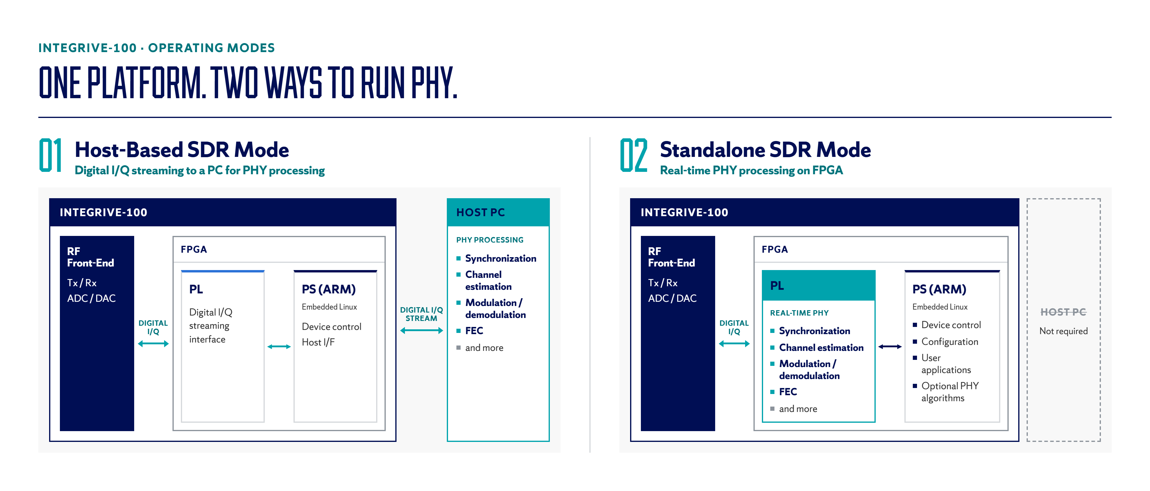
    Integrive-100 supports two operating modes. In Host-based SDR Mode, digital I/Q samples are streamed to and from a host PC for software-based PHY processing. In Standalone SDR Mode, the real-time PHY processing chain runs directly on the FPGA, enabling independent wireless system operation without a host PC.

    Left:

    • Digital I/Q samples are streamed between Integrive-100 and a host PC.
    • PHY functions, including synchronization, channel estimation, modulation/demodulation, and FEC, are executed on the host PC using C/C++, Python, MATLAB or other software tools.
    • Ideal for algorithm development, verification, signal analysis and experimentation.

    Right:

    • Enables easy development and evaluation of PHY algorithms in real RF.
    • Enables product-level validation of PHY, MAC and networking protocols under real-world wireless conditions.
    • Accelerates the transition from validated wireless prototypes to product development.

  • Characterizing SDR RF Performance: EVM, 256-QAM, and Image Rejection

    Jayoung Oh • 10/13/2026 at 23:56 • 0 comments

    My previous logs were about how Integrive-100 can be used to move PHY experiments from simulation to real RF. But this time, I’d like to turn our attention to the hardware. How much impairment is being introduced by the radio hardware itself?

    Real RF hardware introduces phase noise, I/Q imbalance, nonlinear distortion, and other imperfections that are absent or simplified in simulation. As modulation order increases, these effects become more important. If the RF chain introduces too much distortion, it can become difficult to tell whether a performance limitation comes from the algorithm being tested or from the hardware carrying the signal.

    So we characterized the RF performance of the platform, focusing on EVM, 256-QAM operation, and image rejection.

    EVM and 256-QAM Performance

    High-order modulation is a good place to start because it is particularly sensitive to RF impairments.

    In loopback measurements, the radio achieved a combined TX/RX EVM of −35 dB or better, providing approximately 3 dB of margin relative to the −32 dB reference level used for 256-QAM.

    But we also wanted to see what this looked like in an operating PHY rather than relying on the loopback EVM measurement alone.

    For this test, we implemented SIP-DDM, our PHY technology for highly reliable wireless communication, together with Reed–Solomon coding and no retransmission.

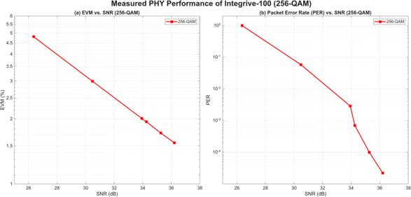
    The figure below shows the measured EVM and packet error rate (PER) as SNR changes.

    Figure 1. Measured 256-QAM performance on Integrive-100 using the SIP-DDM PHY with Reed–Solomon coding and no retransmission: (a) EVM versus SNR and (b) PER versus SNR.

    As SNR increases, EVM decreases while PER drops rapidly. At approximately 36 dB SNR, the measured EVM reaches about 1.55%, while PER falls to around 2 × 10⁻⁵.

    For us, the important part of this test was seeing the RF hardware and PHY processing working together in an actual packet-based 256-QAM link.

    I/Q Imbalance and Image Rejection

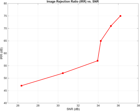
    Another RF impairment we looked at was I/Q imbalance, which can generate unwanted image components that degrade signal quality, particularly in direct-conversion RF systems. Integrive-100 uses digital I/Q calibration to suppress these image components.

    Figure 2. Measured image rejection ratio (IRR) versus SNR.

    As shown in Figure 2, the measured image rejection ratio (IRR) reaches up to 75 dB, providing a reliable RF foundation for PHY algorithm evaluation.

  • Taking Wireless Research Beyond Simulation

    Jayoung Oh • 09/24/2026 at 20:21 • 0 comments

    Integrive-100 in Black Case

    I’d like to explore how the architecture I discussed in the previous post helps us build wireless applications and validate them in real RF environments.

    From Simulation to a Real Wireless System

    Simulation is where many wireless ideas begin. A new PHY algorithm, MAC protocol, routing scheme, or sensing technique can be developed and evaluated under controlled conditions.

    But eventually, we want to answer a different question:

    What happens when we put it into a real wireless system?

    Real RF brings in factors that are difficult to capture completely in simulation, such as RF impairments, synchronization behavior, interference, multipath, changing channels, processing delays, mobility, and interactions among multiple nodes.

    These are some of the reasons why an algorithm that works well in simulation may behave differently when it becomes part of a real wireless system.

    We wanted to make it easier to validate a technology as part of a real wireless system before moving toward dedicated product hardware.

    A Simple Example: An Industrial Wireless MAC

    Consider a new MAC protocol designed for an industrial wireless network. Simulation might show how the protocol performs in terms of latency, reliability, or scheduling. But the intended application may involve multiple wireless nodes operating around metal structures and moving equipment, with interference and constantly changing radio channels.

    With multiple Integrive-100 nodes, the protocol can be implemented as part of a working wireless system and evaluated under realistic traffic, interference, mobility, and RF conditions. If the complete application performs as intended, the results go beyond a successful simulation. They show that the core technology can operate as part of a real system.

    The process looks something like this:

    Simulation → Real-Hardware Implementation → Product-Relevant Validation → Application Validation → Product Engineering

    Beyond a Single Algorithm

    The same approach can apply to PHY algorithms, multi-hop routing protocols, ISAC systems, or AI-enabled wireless applications.

    At the PHY level, a researcher can change the function they want to investigate while using the existing PHY for the surrounding communication chain. With multiple units, the same platform can become an experimental wireless network for testing MAC, routing, coordination, or other multi-node algorithms over real RF.

    Taking It Into the Real Environment

    * Example: Industrial ISAC

    Multiple Integrive-100 units could be configured as 1 Coordinator + N Wireless Nodes. Researchers could then implement their own communication and sensing algorithms and evaluate them in an industrial environment where multipath, metal structures, obstacles, interference, and moving objects become part of the experiment.

    * Example: AI-Connected Wireless Systems

    Integrive-100 can also be connected to an external AI platform, such as NVIDIA Jetson Orin. The AI processor handles inference for sensing, vision, or robotics, while Integrive-100 provides the wireless communication link, allowing researchers to evaluate AI-enabled systems under real communication constraints. 

    From Validation to Product

    Once the core technology and application have been validated in a real wireless environment, product development can begin with much of the technical uncertainty already addressed. 

    This is something we are doing ourselves. We have integrated our own wireless algorithms into Integrive-100 and are testing them in outdoor drone flight tests.

  • Rethinking the PHY Research Workflow

    Jayoung Oh • 09/20/2026 at 02:51 • 0 comments

    From PHY Algorithms to Real RF Validation

    One of the design goals was to make it easier to test an individual PHY algorithm without rebuilding the entire communication chain around it.

    A complete wireless PHY includes synchronization, channel estimation, equalization, modulation and demodulation, FEC, framing, OFDM processing, and RF configuration. In research, however, the focus is often on only one or two of these functions.

    Figure 1. The Tx/Rx processing chain used in Integrive-100.

    When testing a new channel-estimation algorithm, moving it from simulation to RF hardware still requires the surrounding receive chain to be available: synchronization, FFT processing, equalization, demodulation, framing, and data movement.

    We got tired of having to deal with all of that just to test one algorithm. What we wanted was a workflow where the function under development could run in software on the ARM-based Processing System (PS), while the existing FPGA implementation handled the surrounding PHY processing in the Programmable Logic (PL).

    This allows the algorithm to be evaluated within an operating PHY rather than only against simulated or previously captured data.

    Figure 2. An algorithm can first be evaluated in the PS within the working PHY chain and later moved toward a PL implementation when deterministic real-time processing is required.

    The distinction we wanted to make here is between testing an algorithm by itself and testing it as part of an operating wireless link.

    With the complete Tx/Rx chain running, the algorithm can be evaluated at the symbol level using actual transmitted and received RF signals. This makes it possible to observe behavior under practical hardware effects that may not be fully represented in simulation.

    The same approach can be applied to other areas of PHY research, including synchronization, FEC, modulation/demodulation, OFDM processing, and framing. For synchronization in particular, real RF testing involves effects such as timing error, carrier-frequency offset, phase noise, and other RF impairments. For OFDM and waveform development, parameters such as FFT size, cyclic prefix, modulation, and framing can be explored before moving toward a real-time implementation.

    You can select the function you want to investigate and implement or evaluate a new algorithm on the embedded ARM processor, while the remaining PHY functions continue to operate in FPGA logic. In this way, the algorithm is not tested in isolation, but as part of a working PHY over real RF hardware.

    This workflow came from a frustration we kept running into in our own PHY research. I'm curious whether you've had the same experience, and how much a workflow like this could actually make a difference in your research.

View all 4 project logs

Enjoy this project?

Share

Discussions

Jayoung Oh wrote 09/18/2026 at 03:03 • point

The main profile photo with my hand is real. The white case is a prototype, and AI was only used to enhance the photo, but I just replaced it with the original one (thanks for pointing that out). For the black one, I used the white prototype image to try out different colors and add the logo with AI. The final case is still in development, and I'm still deciding on the color.

  Are you sure? yes | no

Matthew wrote 09/17/2026 at 20:06 • point

Why were both images in your details section AI generated?  Theres a SynthID coming from ChatGPT from the 2 images.

  Are you sure? yes | no

Does this project spark your interest?

Become a member to follow this project and never miss any updates