 mircemk
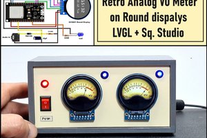
In several of my previous videos I have shown you how to make analog VU meters emulated on different displays. This time I will explain how to make such a project, but now on display modules that contain almost all the components, including the MCU. It is only necessary to add a few passive elements and an LED that will function as a PEAK meter.
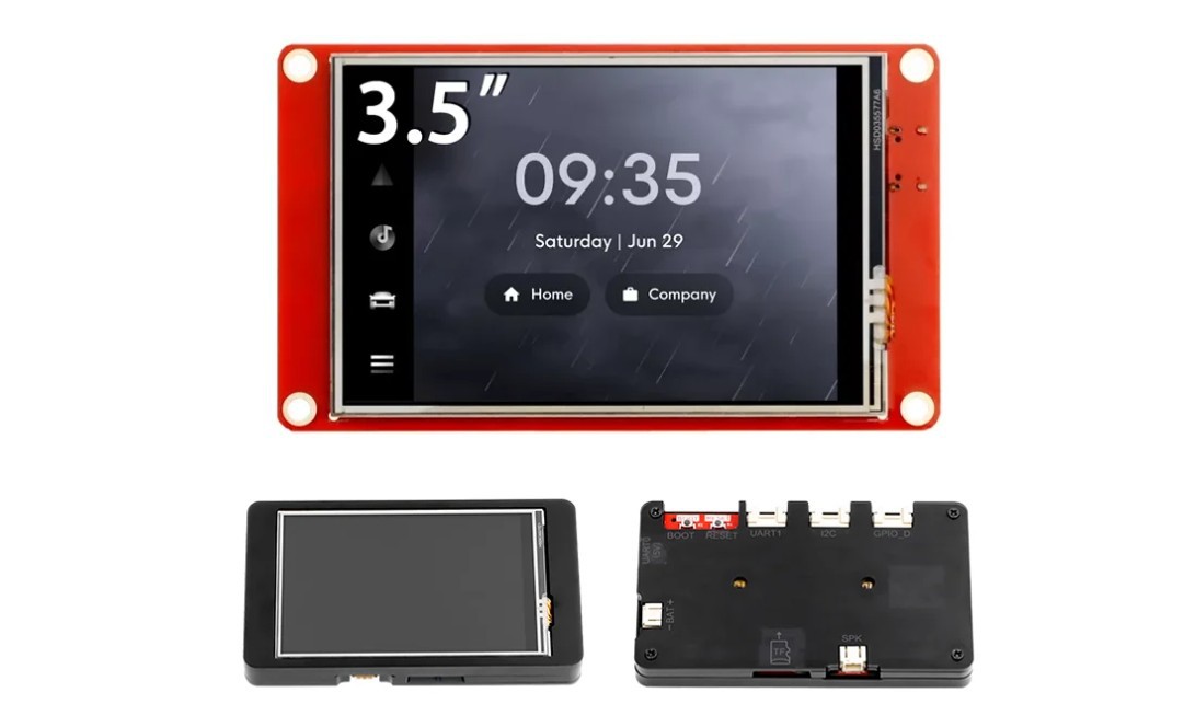
Specifically, in this project I use two CrowPanel 3.5"-HMI ESP32 Displays 480x320 which, together with the precisely made acrylic housings, cost about $15 for each display. For this low price we get a module with impressive features:
- a powerful HMI touch screen with a 480*320 resolution
- ESP32-WROOM-32 module as the main control processor
- integrated WiFi and Bluetooth-compatible wireless functions
- TF card slot,
- multiple peripheral interfaces,
- USB interface,
- speaker interface,
- battery interface, etc.
In this project I will use only a small part of these possibilities.
This project is sponsored by PCBWay. From April 15 to June 15, 2026, PCBWay is organizing KiCad PCB Design Contest on the occasion of the launch of KiCad 10 with enhanced features and improved workflows. There are three grand prizes of $500 cash + a Raspberry Pi 5, as well as a Participation Award, a Raspberry Pi Pico 2. Review the official rules and selection criteria, submit your innovative design, and you could be our next winner. PCBWayand KiCad look forward to seeing your creativity in action!

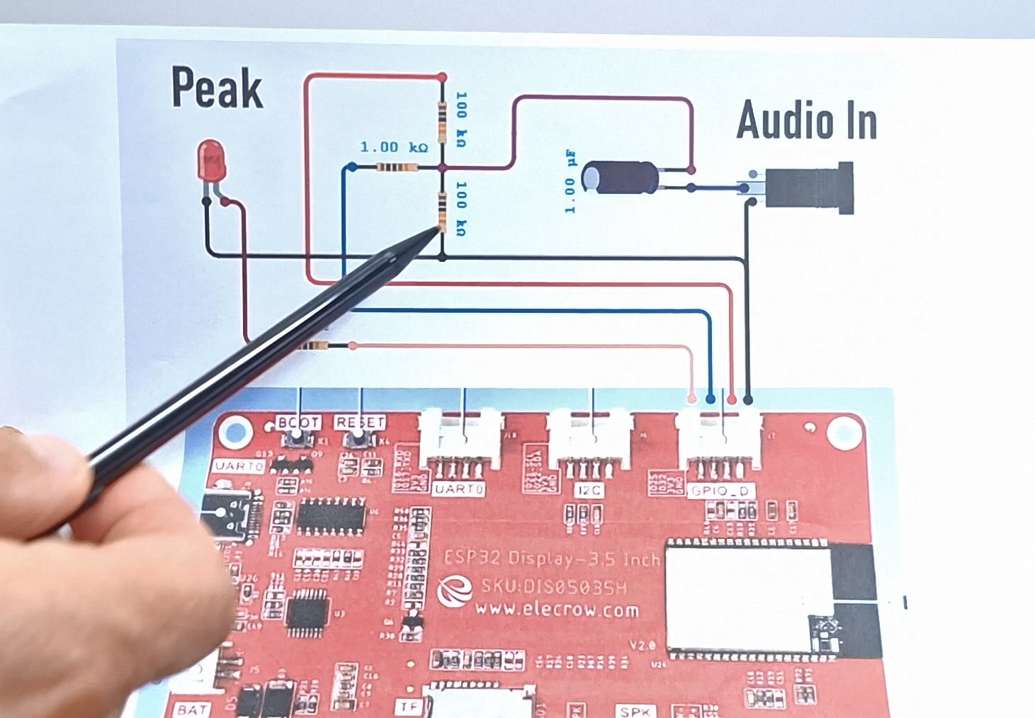
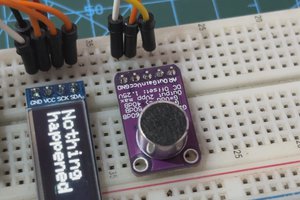
As for the several passive components dedicated to the ADC input of the module, the explanation is as follows. The code is designed to process a pure AC input audio signal. To measure this signal, we need to raise the ADC input to some reference voltage level. We achieve this with the two 100K resistors. Now the signal moves above and below this reference point. The capacitor blocks any DC component, and the 1K series resistor serves to protect the input from a too strong signal. The modules are powered directly from a 3.7V lithium battery or via the USB Type-C connector.
The two channels are identical. The advantage of this configuration with two separate channels with their own microcontrollers is the fact that they are totally independent and there is no interference between the channels.
A few words about the code, it is designed in a way that can be very easily modified, allowing us to set custom behavior of the arrows and pick LEDs according to personal preferences. Let me mention that when creating the graphic part I used LVGL and Squareline Studio, which means that by changing the UI files you can very easily create VU meters with different "faces".
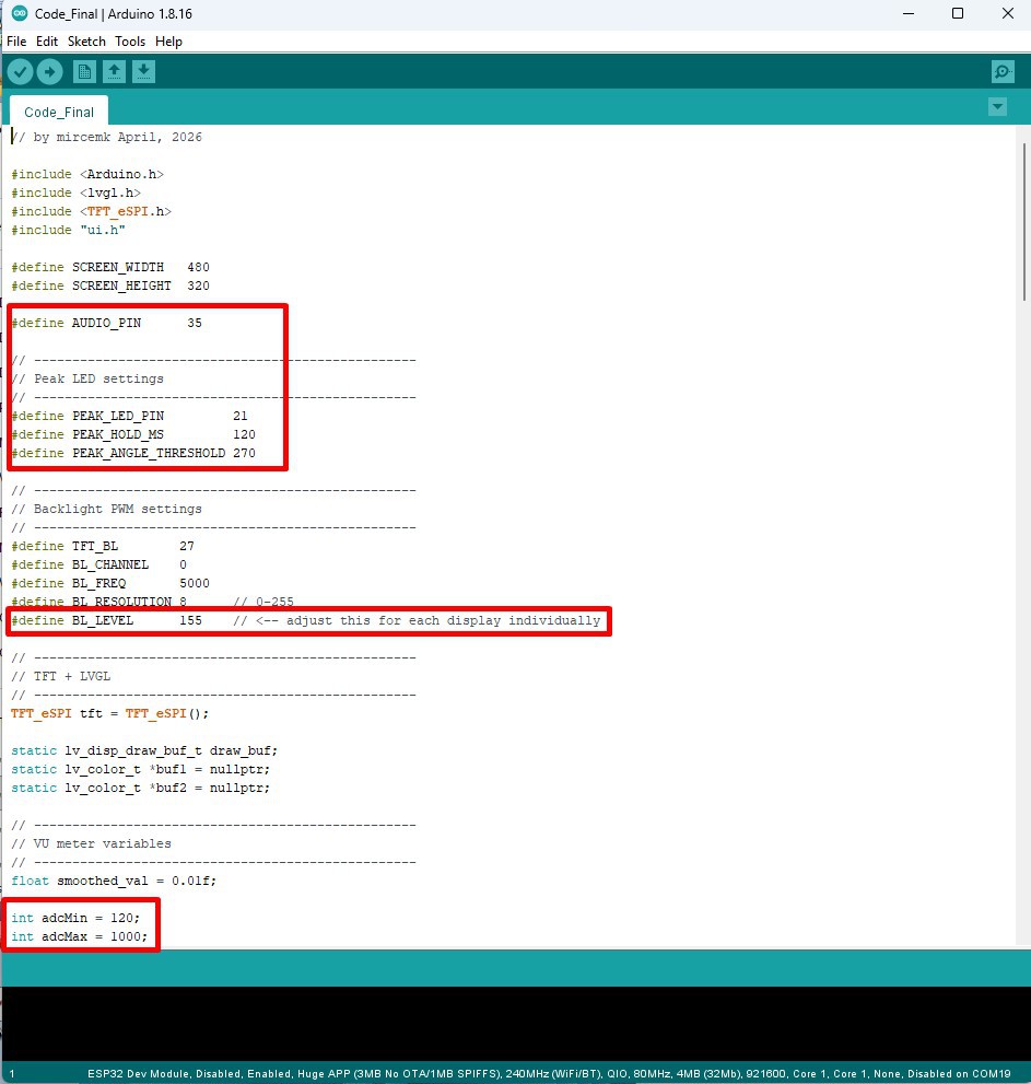
- First, the pins are defined, then PEAK THERSHOLD which sets the LED to light up when the arrow crosses the red field. PEAK HOLD MS is the time during which the LED remains lit in milliseconds. adcMin and adcMax are defined according to the value of the input signal. For a standard input signal of 775mV, these values are 0 and 600.
And these two commands define the arrow's forward and backward movement speeds separately, so that the visual impression can be adjusted according to desire.
It's nice to see how the device behaves in real conditions with different input signals.
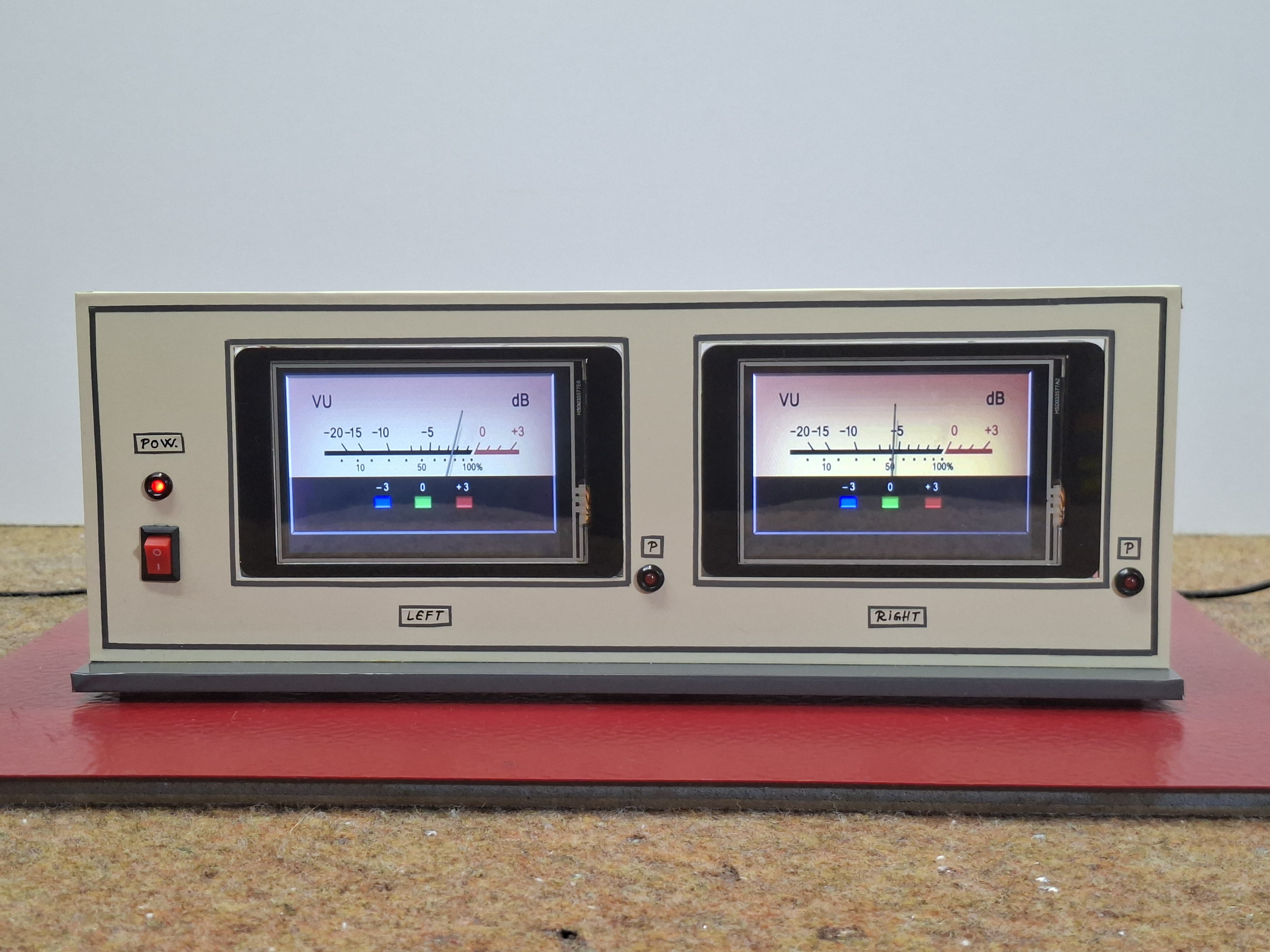
And finally a short conclusion. In this project, I built a fully functional analog-style VU meter using an CrowPanel 3.5"-HMI ESP32 display, and LVGL. Unlike typical digital meters, this one behaves like a real analog VU meter – with smooth needle movement, adjustable attack/release speed, and accurate audio response.
IMPORTANT UPDATE: During the final development of the project, I encountered a problem. Namely, after uploading the code, the GPIO25 and GPIO32 pins, which are located directly on the GPIO_D connector, were constantly at a high level (3V3). These pins were probably used by one of the libraries, so for me the easiest way was to use other free pins. For this purpose, I made leads (soldered wires) directly on the microcontroller...

 Arnov Sharma
 CiferTech
During compiling in Arduino IDE 2.3.20 getting the following error Arduino\VU_Meter_3.5_inch_20_6_2026\VU_Meter_3.5_inch_20_6_2026.ino:6:10: fatal error: ui.h: No such file or directory 6 | #include "ui.h" | ^~~~~~
compilation terminated.
How can this be resolved / where can we get this file.