 Laboratorio Gluón
As stated in the previous post, the design was simple: A microcontroller to read the values read by the ADS1117 ADC, which is connected to the output of the OpAmp chain.
Pretty simple design, which actually seems to work in the µA range. However, during extensive testing, the device several issues began to emerge.
In the image below, the device is working with 1 µA, but analyzing the data from the PC shows the real thruth. The signal captured by the device contains a high 50Hz signal coupled into the actual signal.
(As always more updated info in my blog)
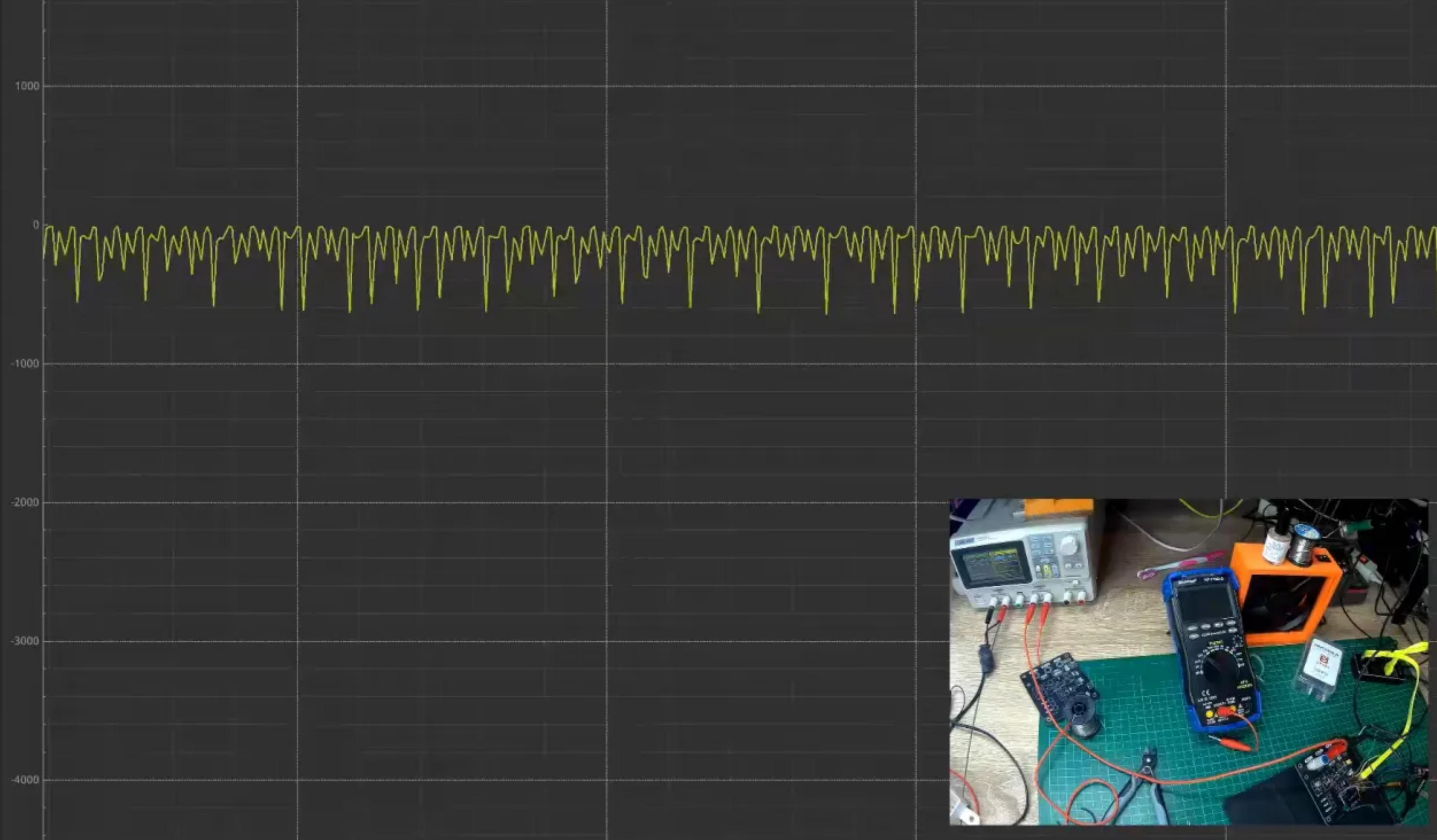
I had heard about this issue, but never experience myself. When working in regular projects, AC coupling usually is not a problem. The hundreds of microamperes flowing though the circuit do not affect the measurements or the device's functionalities. However, in this project, the voltage drop in the shunt resistor is in the range of µA in a 10 $k\Omega$, even the lowest current can create a measurable noise.
The mains coupling is a problem that appears when the mains frequency (in Spain 50 Hz) is capacitive coupled to the circuit. The circuit, the probes, the cabling, everything couples with the main voltage, thus generating a small AC current flow through the circuit. This small current generates the noise
in the measuring shunt.
Solving the AC coupling in this first version of the PCB is not easy. The signal bypassing the parasitic capacity to the mains voltage has to come back to the wall plug, and the easiest way is through our measuring circuit.
In the upcoming news, we will move towards an isolated design with the analog part isolated from the USB part to avoid this issue!
Discussions
Become a Hackaday.io Member
Create an account to leave a comment. Already have an account? Log In.