 mircemk
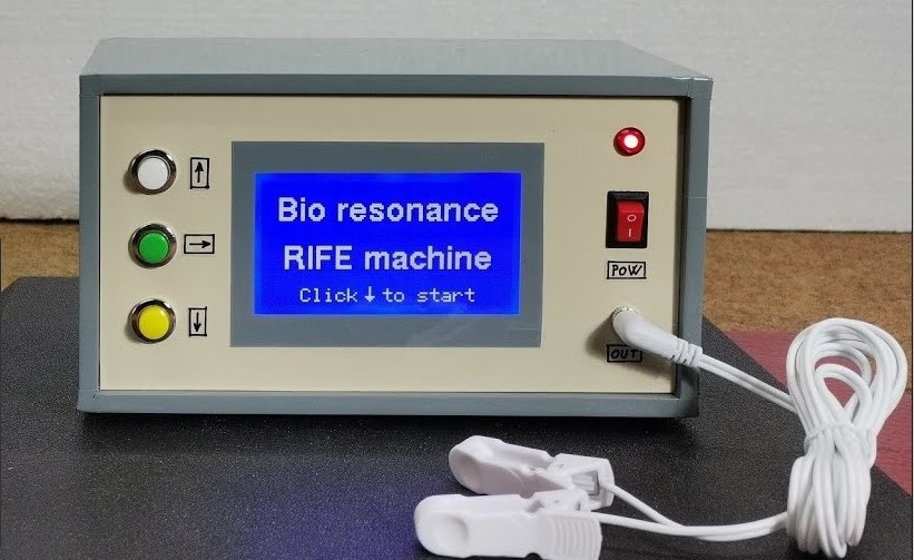
In several of my previous videos, I presented you with different ways to make a Rife Machine, from the simplest with metal electrodes as a medium for the transfer of frequencies, to an advanced Plasma Rife Machine. This time I will stick to the more advanced versions which, like the original device, use plasma as a medium that radiates into the environment.
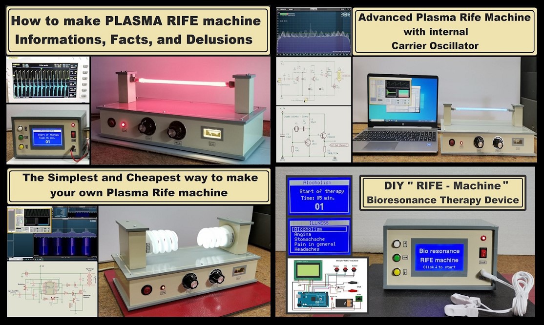
With the previous devices, I mostly used a configuration that consisted of: a carrier signal generator, a modulator, an amplifier, a HV transformer and finally a Plasma Tube. A quality HV Transformer retains its characteristics up to a few hundred kHz, and above this frequency the signal weakens. In the original Rife machine, the carrier frequency is much higher, specifically about 3.1 MHz. What you see in the spectrogram from the previous videos is that 3.1 MHz carrier signal, but significantly weakened due to the characteristics of the HV transformer. That is why very weak parasitic signals are visible around it and in the entire spectrum.
I spent more time thinking about how to solve this deficiency, and I came up with the idea of using a Tesla Coil to generate a clean carrier signal.
Since the Tesla Transformer is actually a high voltage generator, with it we can directly drive the plasma tube without the use of an amplifier and HV Trafo. Also, the tesla transformer can work even at frequencies of several tens of MHz without any problem. In fact, the original Rife machine works in roughly the same way. Instead of vacuum tubes like the original, I use modern solid state components. Next, as can be seen from the schematic diagram, I perform frequency modulation of the oscillator (carrier) with an external "Rife" frequency.
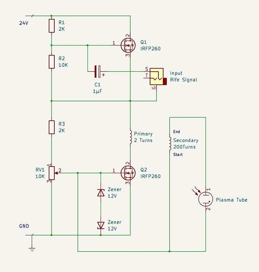
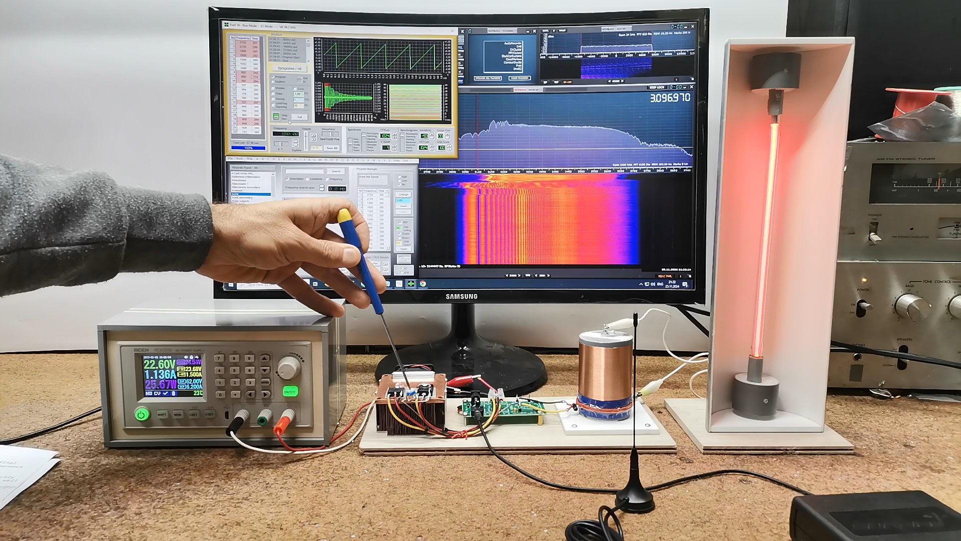
Now let's focus specifically on this new project. This is the Rife Tube driver, which is actually a modulated Tesla Coil. I set the resonant frequency of this transformer to be exactly 3.1 MHz using one of the online calculators for this purpose. The primary coil consists of 2 turns around the secondary with an insulated copper wire with a cross section of 1mm. The secondary coil is wound on a body with a diameter of 5 cm and contains 200 turns of varnished copper wire with a cross section of 0.35 mm.
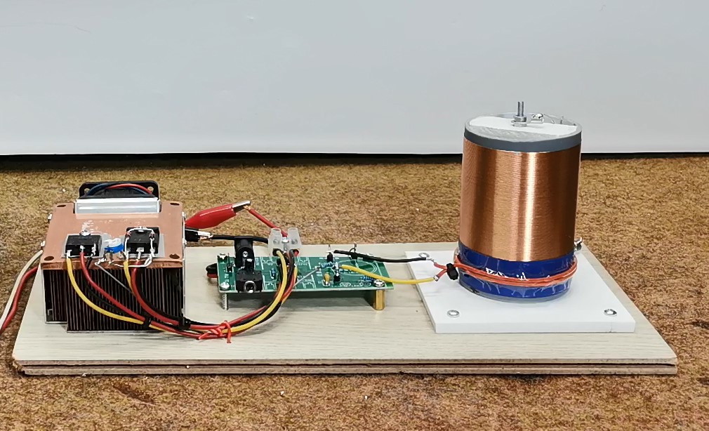
One mosfet drives the primary coil, actually the transformer itself, and the other mosfet is a modulator and modulates the supply voltage with a "Rife" frequency. Otherwise, this is the simplest practical way of modulation. The mosfets are mounted on a massive heatsink for better heat dissipation. Since this is a test sample, I am using a laboratory power supply with a voltage of 24V and a constant current of 1.5A, in order to protect the mosfets. Now let's first perform measurements and look at the characteristics of the driver (tesla coil) without a connected plasma tube. Since I do not own a classic spectrum analyzer, as usual I will use my SDR radio SDRPlay for this purpose, together with the accompanying software SDRuno. Through small antenna I will receive the signal emitted by the Tesla transformer, and then I will analyze it in the software. As a source of Rife frequencies, we can use various commercial or non-commercial devices, and in this particular case I use the excellent Frex16 software which is free and you can find it on the Spectrotek website.
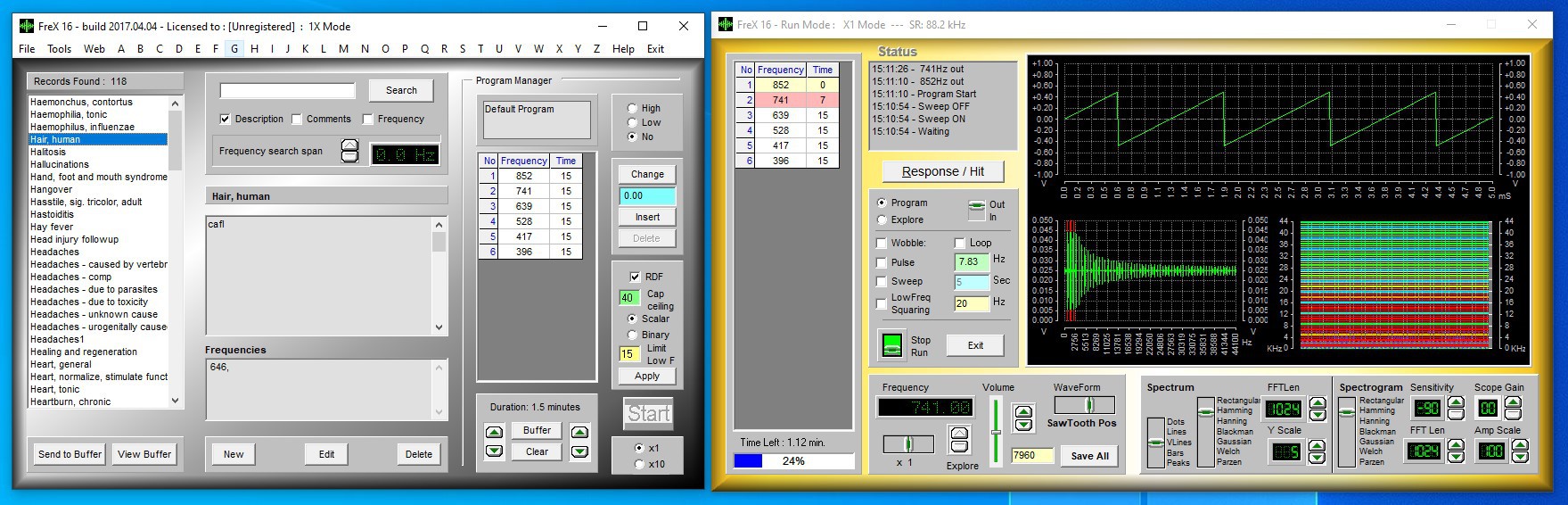
This software also contains a database of many ready-made frequency sequences for treating various diseases.
Of course, you can also use the Arduino device for which you can find a detailed description of the construction in one of my previous videos.
First we start the Tesla coil and adjust the small trimmer potentiometer to a position where the device draws a current of several hundred milliamperes. This adjustment is made only when first turned on. Regarding the making of the secondary coil, according to the calculations that I performed on online calculators, the frequency it radiates should be around 3.1 MHz. If we look at the spectrum analyzer, we see that the frequency is very close to 3.1 MHz.
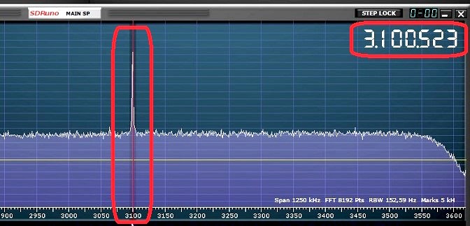
Much more important is the fact that the signal is crystal clear, covers a small range, and there are no parasitic oscillations around it at all, which was not the case with previous versions made with a HV transformer. Also, now the range of radiation (power) is much larger. We can notice that if we bring an object closer to the Tesla transformer, the oscillation frequency will change, in fact it will decrease.
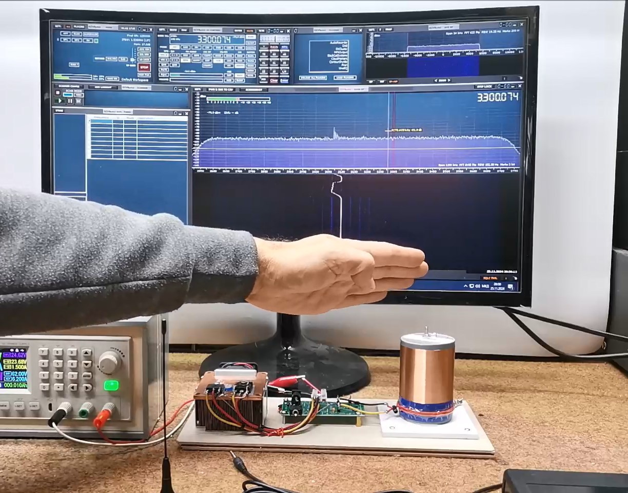
The reason for this is the increase in the capacitance of the secondary coil under the influence of the approaching object. As we will see later, the same thing will happen when we connect the plasma tube. Therefore, when designing a final product, we should take this fact into account, and calculate a proportionally higher oscillation frequency in the "empty from" state, so that when we connect the plasma tube the frequency is exactly 3.1 MHz. This is achieved by reducing the number of turns on the secondary, so that we can relatively easily perform it experimentally.
Now I will bring different frequencies from the Frex program to the modulation input of the Tesla coil and we will observe the modulated output signal for different input frequencies.
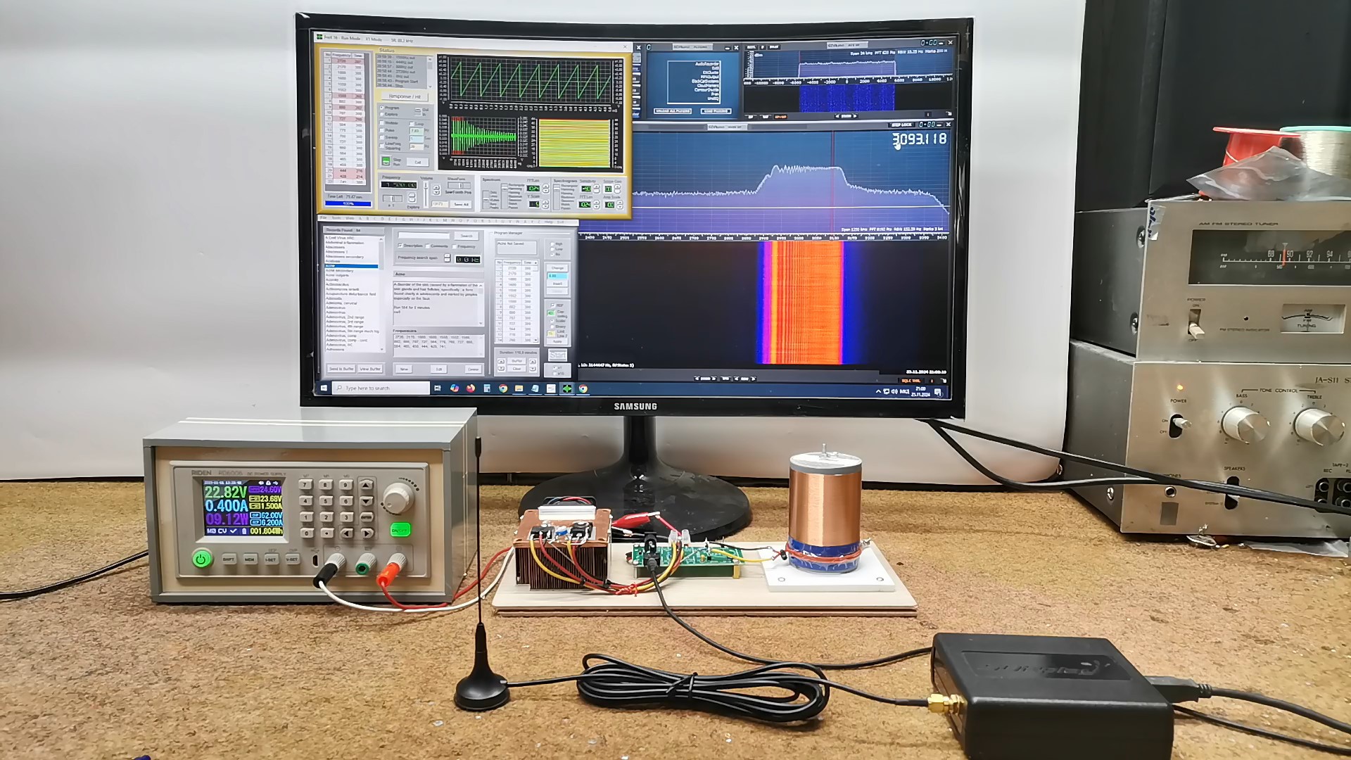
This is actually the most interesting part, the modulated final signal that is radiated into the environment is incredibly homogeneous and clean. I can also clearly see its harmonics, which are also located exactly where predicted according to the calculations (2f,4f... for even, as well as 3f,5f for odd harmonics).
Now let's try the same thing but with a Plasma tube connected. In this case I set the carrier frequency at 3.7MHz, because when I Activate the Plasma tube with modulation signal, the carrier frequency will be exactly 3.1 MHz.
As for the plasma tube itself, mine is filled with argon gas. I mounted it on this half-cylinder support primarily for mechanical protection but also for a better visual effect. If we place aluminum foil on the inside, then the tube will radiate only on the front side.
I just want to point out that my personal subjective opinion about the effect of this device on health is completely negative, and I think that this device "heals" just as much as an ordinary CFL bulb, but everyone has the right to believe or not believe in something. Only the hazy red plasma can have a Placebo effect on the patient, which is not a negligible effect after all. I am exclusively interested in the technical side, especially due to the fact that these machines are advertised as miraculous and based on that are sold at unrealistically high prices, and all of this is ultimately reflected in the patients who pay huge sums for such treatment. With this series, I would like to make it a little clearer to people that this is a relatively simple electronic device that any slightly more experienced electronics technician could make.
And finally, a short conclusion. First of all I want to tell you that this is the most advanced version so far, and is based on original Rife project, but with modern semiconductors. As for the components used, and the circuit diagram, this is the simplest version of the Plasma Rife machine. However, for the making a stable Tesla coil, at least some basic experience in this area is required, as well as the use of laboratory power supplies with a constant voltage and constant current option, which will "save" a lot of Mosfets during the manufacture. On the other hand, the signal generated by this version of the Plasma Rife machine is incredibly clean and stable and can be compared with any commercial device, which by the way costs several thousand dollars.