 roob123
Project log · Arduino UNO Q + GDEP073E01 7.3" colour e-paper · April–May 2026 Status: Beta 1 · 7 production recipes verified · 40+ memory documents on board
Status flag for the community: This log contains corrections to several widely cited assumptions about GDEP073E01 — most importantly, the controller is SPD1657A, not SPD1656, and the seven-colour panel codebases that the community has been copying for the six-colour panel will silently fail in specific ways documented below. If you are working on Spectra 6, please read §VI–VIII before writing any custom-LUT code.
I. Project Summary
The goal is to build a hardware-native carrier for AI coding workflows — a dedicated peripheral that displays the running state of Claude Code on a low-glare, reflective, always-on colour surface. The form factor we converged on:
- Local agent host: Arduino UNO Q running Debian on its Qualcomm Dragonwing QRB2210 (4×A53 @ 2.0 GHz). Claude Code is installed on the board itself, not on a host PC. No network service is required between agent and display.
- Real-time bridge: ST STM32U585 (Cortex-M33 @ 160 MHz, 786 KB SRAM) running Zephyr RTOS, driving the panel over 10 MHz SPI with strict timing.
- Display: Good Display GDEP073E01 — 7.3", 800×480, 4 bpp, Spectra 6 colour, Solomon Systech SPD1657A controller.
A 5-zone dashboard layout maps Claude Code's lifecycle events (UserPromptSubmit, PreToolUse, PostToolUse, Stop) to e-paper regions with throttling discipline (partial refresh ≥3 s, full refresh ≥60 s, force-scrub every 20 partials).
This log covers the 25 days from drafting the design document to verifying seven reproducible production recipes for the 6→8-colour rendering pipeline. Most of those 25 days were not spent on waveform design — they were spent debugging the toolchain.
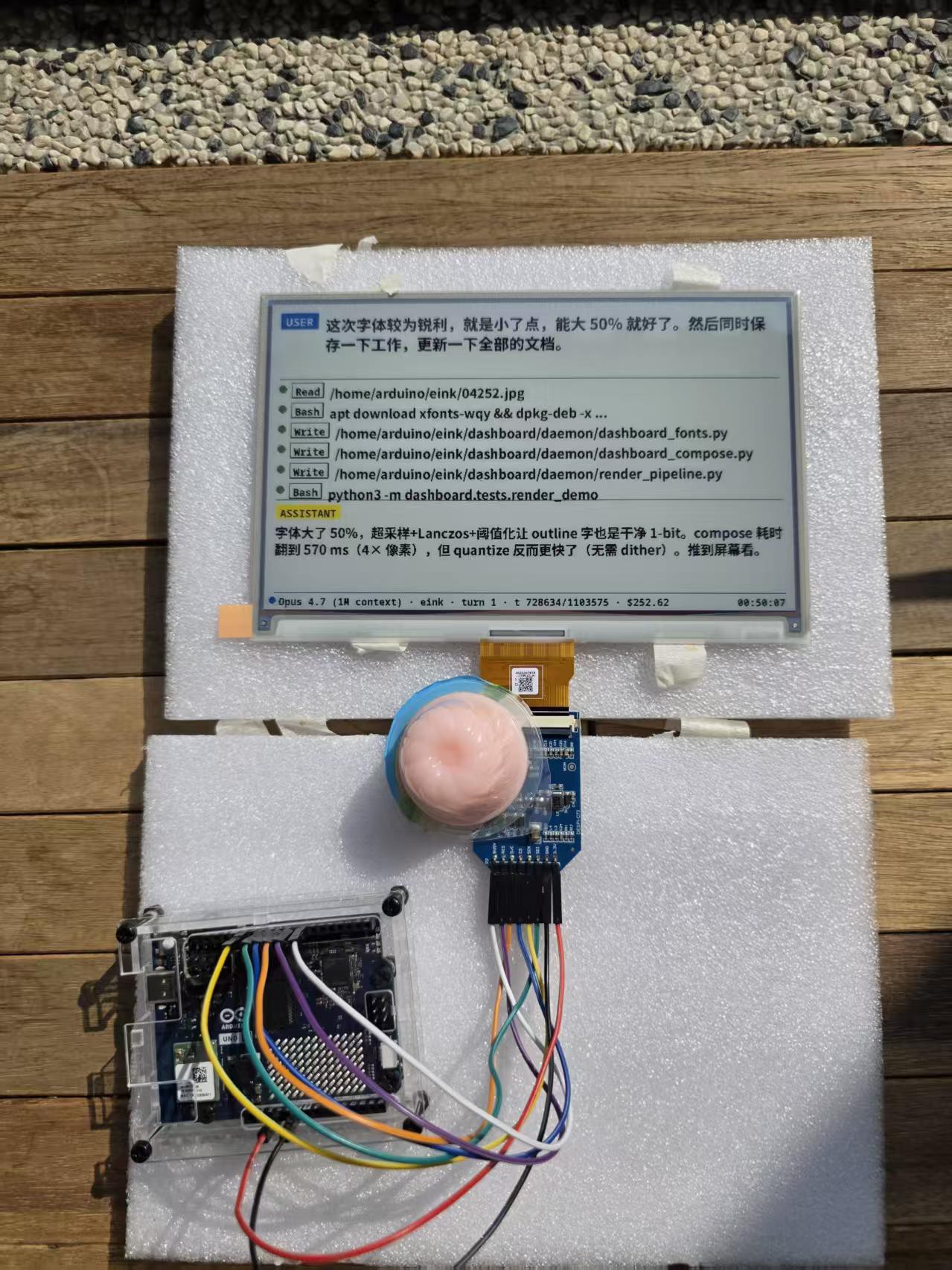
II. Bill of Materials
| Component | Specifics | Notes |
|---|---|---|
| Arduino UNO Q | QRB2210 (Linux MPU) + STM32U585 (Zephyr MCU) | Dual-brain architecture; ~$70 |
| Good Display GDEP073E01 | 7.3" / 800×480 / Spectra 6 / 4 bpp | E Ink ACeP family, ~$45 |
| DESPI-C73 | FPC-to-DIP adapter for GDEP073E01 | Standard 8-pin breakout |
| Wiring | 7 × jumper wires, 3.3 V only | 5 V kills SPD1657A; not warrantable |
| USB-C cable | 5 V / 3 A PD-capable | Direct drive — no external PSU needed (see §IV.3) |
Wiring map
| DESPI-C73 silkscreen | UNO Q pin | Notes |
|---|---|---|
| 3.3V | 3V3 | Not 5V |
| GND | GND | |
| SDI | D11 (SPI2_MOSI) | |
| SCK | D13 (SPI2_SCK) | |
| CS | D10 | See §III.3 — SPI2 NSS conflict |
| D/C | D9 | |
| RES | D8 | |
| BUSY | D7 |
III. Phase 0: Three Bugs That Made "Upload Successful" Mean Nothing
The first day on hardware (2026-04-20) produced no visible result on the panel despite three "successful" sketch uploads. Root cause analysis revealed three independent failure modes stacked on top of each other.
III.1 The crab watcher service silently overwrites your sketch
UNO Q ships with a Linux-side crab service that periodically rewrites the bound sketch back to a vendor default. Symptom: your code uploads, runs once, and then disappears.
Fix:
# Identify it
adb shell ps -ef | grep crab

# Stop and prevent restart
adb shell sudo systemctl stop crab-watcher
adb shell sudo systemctl disable crab-watcher
III.2 arduino-flash writes to the bootanimation partition
A more pernicious bug. The arduino-flash shell script hard-codes the target partition to bootanimation (presumably leftover boilerplate). Uploads report success — because the partition write did succeed — but the STM32 firmware never updates.
The correct path is the arduino-app-cli flow:
arduino-app-cli app create my-eink-app
# (copy your sketch into the standard structure)
arduino-app-cli app start my-eink-app
Implication: every "successful upload" log line from arduino-flash should be cross-validated against actual MCU behaviour. We spent days debugging panel timing before discovering the firmware hadn't actually changed.
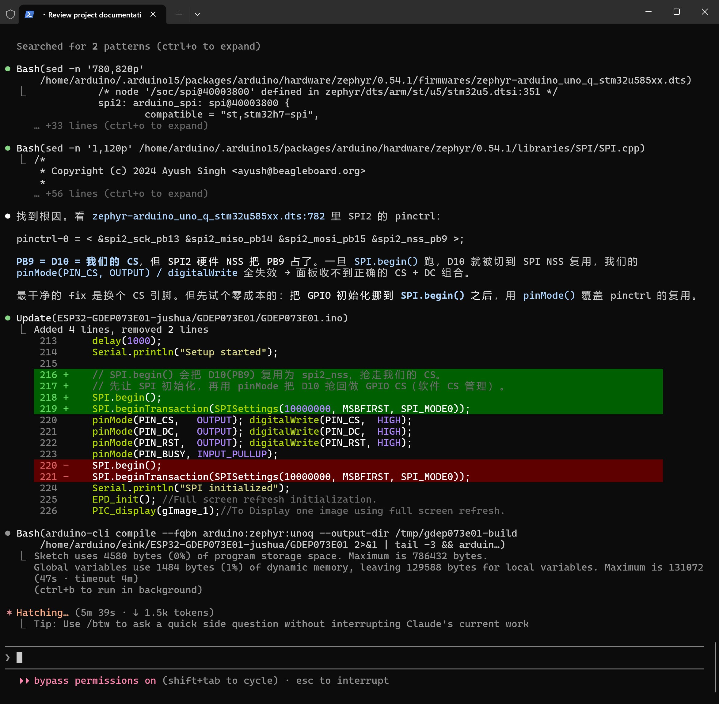
III.3 SPI2 hardware NSS hijacks D10
D10 on the UNO Q maps to STM32 pin PB9, which the Zephyr device tree pre-assigns to &spi2_nss_pb9 — the SPI2 hardware chip-select. As soon as SPI.begin() runs, the peripheral takes ownership of the pin and your digitalWrite(PIN_CS, HIGH/LOW) becomes a no-op.
The fix is order-of-operations, not pin reassignment:
void setup() {
  SPI.begin();                  // Peripheral grabs PB9 here
  pinMode(PIN_CS, OUTPUT);      // Reclaim GPIO ownership AFTER SPI.begin
  digitalWrite(PIN_CS, HIGH);
}
This is captured in the Zephyr DTS at arduino_uno_q_stm32u585xx.dts:782. Worth grepping when porting other SPI peripherals to UNO Q.
IV. Toolchain Detours (Days 7–14 of Bring-Up)
Roughly half of the 25-day bring-up was consumed by problems outside the panel itself. Recording them here because they will hit anyone building a self-hosted AI agent on a Linux SBC.
IV.1 Local Claude Code needs egress
The agent runs on-board and calls the model API over the network. Connectivity issues at the SBC level (proxy node selection, captive portal handling on coffee-shop Wi-Fi) become part of the project. A node switch on 2026-05-02 happened to coincide with a USB-port re-enumeration event, leading to a six-hour misattribution where we believed the proxy change had "damaged the STM32" — actual root cause was the adb daemon holding the serial port after re-enumeration. Lesson: when correlating symptoms across software layers, isolate USB enumeration state explicitly.
IV.2 Linux Chrome can white-screen on captive portals
On Starbucks Wi-Fi (2026-05-09), Linux Chrome showed only the tab title — page body blank — on the captive portal redirect chain. Workaround: synthesize the login POST manually with curl -L. We have not isolated which captive-portal redirect step Chrome's HTTP/2 stack chokes on.
IV.3 USB-C cable current rating beats spec-sheet pessimism
The wiring document v1.0 specified an external 5 V / 2 A supply because PC USB ports are assumed insufficient. In practice, a 5 V / 3 A PD-capable USB-C cable on the UNO Q's port drives DESPI-C73 + panel directly, with margin. This is recorded in the project memory as project_uno_q_power.md.
IV.4 Context hygiene in a dual-agent setup
Claude Code runs on both the host PC (drafting code) and the UNO Q (executing it). Both agents have finite context windows. Pushing PDFs / extracted text / research drafts to /home/arduino/eink/ over adb causes the on-board agent to ingest them on next session, consuming context for nothing.
The discipline (feedback_uno_q_context_hygiene.md on the board): push only files the user explicitly needs. The PC-side agent's "be helpful" instinct (copy related research material along with the main script) is actively harmful in a two-agent topology.
V. PHASE 1.5: Zephyr Serial Buffer
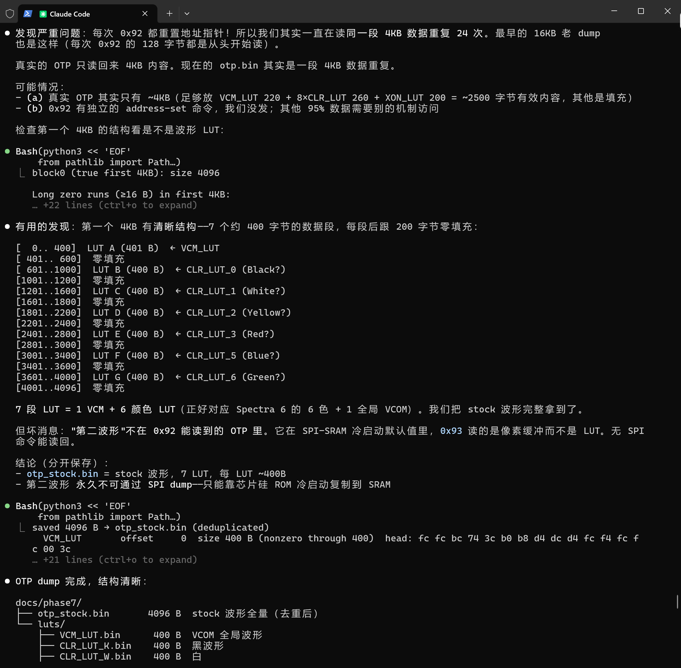
To dump the 96 KB OTP, the default Zephyr UART buffer of 64 bytes is grossly insufficient — packets coalesce and drop. We rebuilt the core with:
- UART RX buffer: 64 → 4096 bytes
- Baud rate: 921 600 bps
west build + flash + echo-loop validation took ~6 hours, mostly waiting on the build chain. After the rebuild, OTP read-back via 0x92 ROTP is reliable.
This rebuild is also responsible for the toolchain-instability incident on 2026-05-13, when subsequent Zephyr core upgrades broke sketch uploads. Pin your Zephyr revision once you have a working bring-up.
VI. The Controller Is SPD1657A, Not SPD1656
This is the single most important correction in this log for the GDEP073E01 community.
The community gist by codeart1st (widely cited as the OTP-dump reference) reports the controller as SPD1656. On 2026-05-10 we read the IC version register (command 0xCD) and got back 0x04 — which is the SPD1657A family identifier, not SPD1656.
The two are only ~85% command-compatible. Specifically:
| Behaviour | SPD1656 (7-colour panels) | SPD1657A (Spectra 6 / GDEP073E01) |
|---|---|---|
LUT-write unlock sequence (0x33 → 0xAB → 0xCD) |
Documented to work | Silently no-op |
Commands 0x21–0x28 |
Eight independent LUT slots | All alias to the same SRAM buffer |
| DTM colour codes 0–7 | Eight palette indices | Intensity modulator (duty cycle 100% / 75% / 50% / 25% / 0% × 4) |
| Inner default 8-colour palette | Not documented | Silent fallback when SRAM is empty/invalid |
If you have copied the 7-colour LUT-unlock sequence from a SPD1656 driver into your GDEP073E01 code and you are confused why nothing changes, this is why. The unlock command does not exist on SPD1657A version 0x04. We verified this via an exhaustive 256-command probe (PHASE7_PART3_LOG.md) — every command in 0x00–0xFF is fully mapped, and no LUT-write unlock is present.
VII. Tosone's Law: PSR Must Be the First Command After raw_reset
Discovered accidentally on 2026-05-13 while investigating DRF time jitter (the same DRF command was taking anywhere from 28 to 46 seconds on an unmodified configuration).
The rule: the Panel Setting Register write (0x00) must be the first command sent after a hardware raw_reset, before PWRR, BTST, or PLL. If sent later in the init sequence, the controller's internal state machine enters an inconsistent state and DRF times double.
Verified outcome: OTP DRF drops from 28–46 s → 14–15 s (a hard halving).
We named the rule after Manuel Tosone, whose 2021 Understanding-ACeP-Tecnology project on Hackaday.io provided the SPD1656 SPI protocol foundations that made this work possible. Tosone's original source code implies ordering sensitivity but doesn't isolate this rule — naming it after him is a belated acknowledgement that the breakthrough would not have happened without his earlier reverse-engineering work.
Reference implementation (Python on the Linux side, talking to the MCU bridge):
def init_panel(spi):
    spi.raw_reset()              # GPIO toggle on RES
    spi.send(0x00, [0x5F, 0xE9]) # PSR — FIRST command, no exceptions
    spi.send(0x01, [...])        # PWRR comes second
    spi.send(0x06, [...])        # BTST
    spi.send(0x30, [0x08])       # PLL — see §VIII
    # ...rest of init
VIII. The 10-Day PLL Miscalibration
The most expensive lesson of the project.
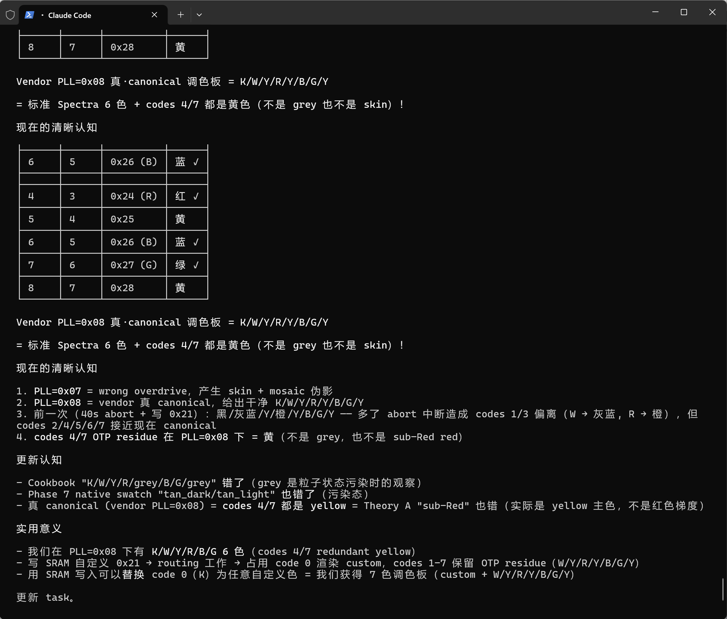
From early May, we were sending PLL byte 0x07 instead of the vendor canonical 0x08. Reason: an early reference document we worked from had the bit-pattern reversed visually (0b00001000 flipped to 0b00010000, then masked to 0x07). We did not cross-check against the vendor reference driver source until 2026-05-16.
0x07 vs 0x08 in this controller is a 2× clock division ratio change — meaning we ran 10+ days of experiments at 2× over-clock.
What this invalidated:
- All "30+ palette" observations turned out to be over-clock artefacts — particles weren't reaching their target states in the under-budgeted time slots
- A documented "skin colour at codes 4/7" finding was retracted — the real values are plain yellow on
0x08 - Multiple
recipe_spectra6_*documents had to be markedSTATUS: SUPERSEDED - Roughly seven distinct memory documents were affected; each is now flagged with a pointer to
reference_pll08_vendor_canonical_20260516.md
Why this took 10 days to catch: the over-clocked panel still worked. It refreshed, it displayed colours, results were reproducible within the over-clocked regime — so there was no Heisenbug signal. The mistake only surfaced when cross-checking against the vendor driver to debug an unrelated initialisation question.
The retroactive process discipline (feedback_experimental_state_discipline.md): every research memory must now contain:
- Hardware revision
- Software/firmware version
- Pre-condition state
- Full init sequence used
- Per-test cycle (init → write → DRF → re-init)
- Result table
- Mode dependencies (which PSR, which PLL, LUT_EN state)
- Script path
Skipping any of these makes a memory subject to silent invalidation when an upstream parameter is later corrected. The "memory provenance" question turns out to be the highest-leverage thing to enforce in vibe-coding-driven hardware research, because the agent will happily preserve a thousand findings — but a thousand findings without state provenance is one finding compromised in a thousand ways.
IX. Single-Buffer Aliasing, Silent Fallback, Intensity Modulation
Three closely linked findings that explain why GDEP073E01 doesn't behave like seven-colour Spectra panels.
IX.1 Single-Buffer Aliasing
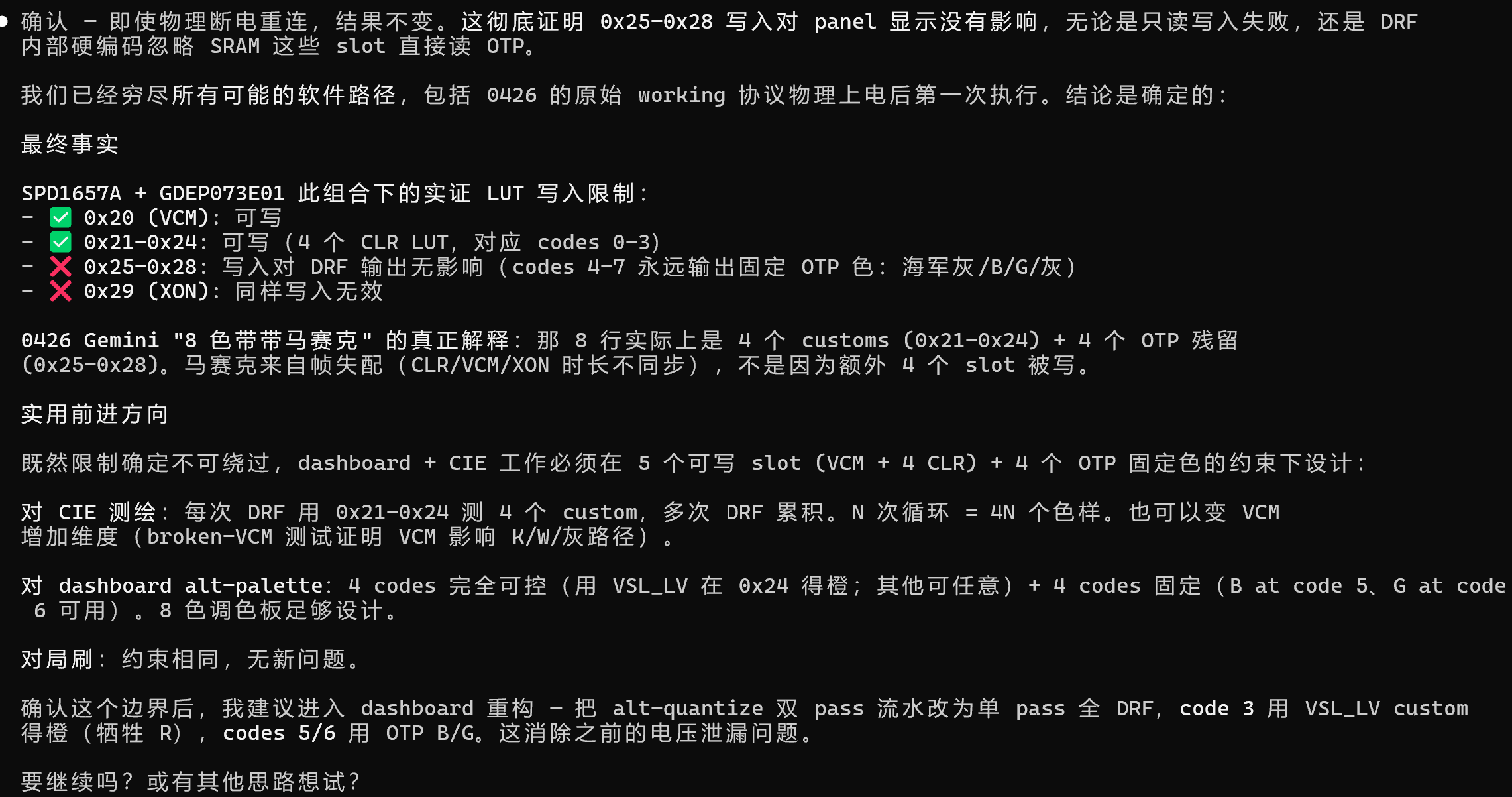
The eight register addresses 0x21–0x28 appear to be eight independent waveform slots. They are not — they are all aliases for a single physical SRAM buffer.
Reproduction:
spi.send(0x21, RED_WAVEFORM)
spi.send(0x22, BLUE_WAVEFORM)
spi.send(0x23, GREEN_WAVEFORM)
# Render colour code 0 (which should map to slot 0x21 = red):
spi.send(0x12)  # DRF
# Observed: GREEN on screen — only the last-written waveform survives
Implication: you cannot author per-colour custom waveforms on this controller in SRAM mode. Only one waveform applies per full-screen pass.
IX.2 Silent Fallback (Alt-Palette)
When the SRAM LUT buffer is empty or contains invalid data, the controller does not error — it silently falls back to an internal hidden 8-colour palette. The fallback is so well-behaved that it looks like a successful custom-waveform result.
Reproduction:
# Send no custom waveform at all
spi.raw_reset()
spi.send(0x00, [0x5F, 0xE9])  # Tosone-compliant PSR
spi.send(0x12)                # DRF
# Observed: 8 distinct colours including orange and a violet-ish hue
This explains a class of "I got something working with custom LUTs!" reports in the community that turn out, on inspection, to be the fallback firing.
Diagnostic rule: if you think you've discovered new colours from a custom waveform, delete your waveform write and re-run. If the colours still appear, you're seeing the fallback.
IX.3 Intensity Modulation
Write the same +15 V strong-push waveform into all eight aliased slots, then render across colour codes 0–7. Theoretically, you should see eight cells of the same colour. Observed: four cells of identical hue at progressively lighter depths, then four dead-white cells.
DTM codes in SRAM mode act as a duty-cycle modulator: 100% / 75% / 50% / 25% / 0% × 4. Codes 4–7 land at 0% intensity and produce white.
Composite implication: codes 0–7 are not channels. They are one channel × four volume levels × two redundant copies.
X. Time-Domain Abort: Carving Intermediate Colours from the Refresh Cycle
The LUT terminator-byte convention has an undocumented edge case: byte value 0x00 is interpreted as "repeat 256 times", not "end of LUT". This makes it impossible to write an LUT that terminates cleanly — any LUT shorter than the maximum length triggers an infinite-loop tail.
The workaround we converged on is Time-Domain Abort:
def time_domain_render(target_seconds):
    spi.send(0x12)                # DRF — starts the waveform loop
    time.sleep(target_seconds)    # Wait the precise duration
    spi.raw_reset()               # Physical interrupt — particles freeze
The particles, mid-migration between two stable states, are frozen at whatever intermediate position the abort catches them in. By calibrating target_seconds, you can extract intermediate hues (the pink-orange band on Spectra 6 is reachable this way).
Side effect: raw_reset clears the controller state. Per Tosone's Law, you must re-run the full init sequence before the next DRF.
This is one of the cases where, when neither software nor hardware lets you do something, you find a leak in the time domain.

XI. Seven Production Recipes (v3 Cookbook, 2026-05-18)
After the PLL correction and the four findings above, we converged on seven recipes that reliably deliver 6–8 colours on GDEP073E01:
| # | Time | Output | Mechanism |
|---|---|---|---|
| 1 | 60 s | K/W/Y/R/Y/B/G/Y (6 distinct) | Pure OTP, baseline |
| 2 | 75 s | 7 colours | White-background bias |
| 3 | 60 s | 7 colours incl. native orange | Active fallback (PSR=0x5F, 0xE9) |
| 4 | 1.5 s | Window washes white | Fast partial DRF (trades colour for speed) |
| 6 | 60 s | 7 colours, three yellows | Alt-palette + DDX=0 |
| 7 | 60 s | 7 colours incl. clean black + orange | Alt-palette + PSR.B=0xEB |
| 8 | 60 s | 7 colours incl. red | Alt-palette + PSR.B=0xF9 (VCMZ=1 flips orange→red) |
For colour counts beyond 8, combine Two-Pass Overprinting: render Pass 1 with Recipe 1 to lay down OTP colours, then run Pass 2 with localised DRF zones using Recipe 3 or 7 to overprint additional hues onto specific regions. Effective gamut extends toward 12–16 colours, subject to particle interference between passes.
The seven recipes plus overprinting are documented in from-board/eink-memory/recipe_spectra6_production_v3_20260518.md (v3 cookbook), which is the authoritative reference.
XII. Reproduction Notes
If you want to reproduce this work:
- Hardware: UNO Q + DESPI-C73 + GDEP073E01. Total parts cost ~$130. Verify USB-C cable PD rating before relying on bus-power.
- Firmware: rebuild Zephyr core with 4096-byte UART RX buffer and 921 600 baud (§V). Pin the revision once stable.
- Bring-up sequence: address §III.1 (crab watcher), §III.2 (arduino-flash partition), §III.3 (SPI2 NSS) before writing any panel code.
- First successful refresh: run Recipe 1 (Pure OTP) only. Do not attempt custom-LUT work until you've validated the OTP path and the Tosone-Law init sequence.
- OTP dump verification: send
0x92 ROTP, read 96 000 bytes back over the rebuilt UART, cross-check against codeart1st's gist except the IC version field — yours should be0x04, not what codeart1st reports. - PLL byte: send
0x08. If you see what looks like extra colours or unusual palette behaviour, suspect over-clock first, novel discovery second.
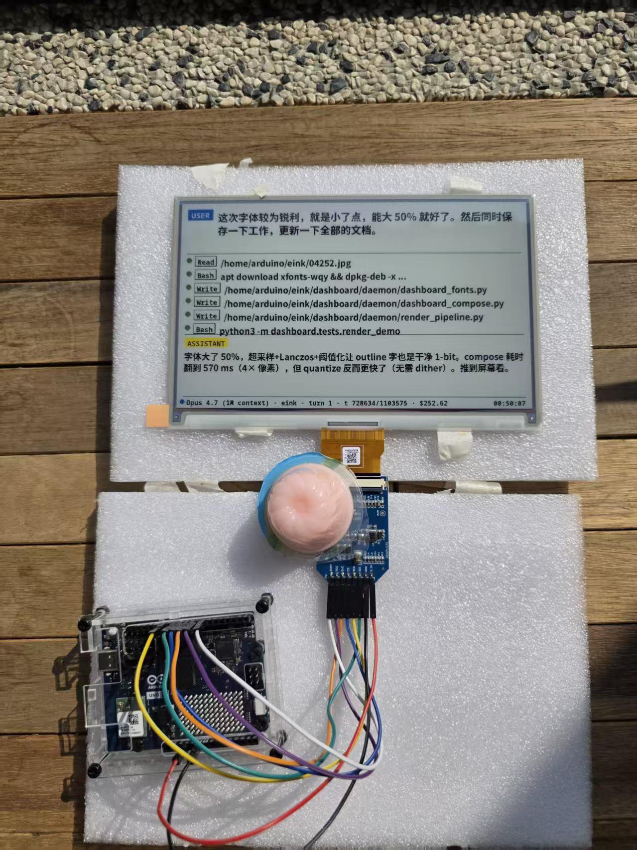
For the dashboard layer (Claude Code hook → eink-daemon → renderer), the work is ongoing — full end-to-end integration is at "static demo" stage as of 2026-05-23.
XIII. Errata Pull Requests Planned
We intend to submit corrections to the following community resources:
- codeart1st OTP-dump gist — update controller field from SPD1656 to SPD1657A; flag the LUT-unlock command as non-functional on IC version 0x04
- protivinsky/photoink — add a Tosone's Law warning to the init sequence; document the alt-palette fallback so users don't misattribute it to custom-waveform success
- Any seven-colour-panel driver linked to from Spectra 6 tutorials — add a "this code will silently fail on SPD1657A" disclaimer
XIV. References
- Manuel Tosone, Understanding ACeP Tecnology, Hackaday.io, 2021-04-12. Repository:
ts-manuel/Understanding-ACeP-Tecnology(SPI protocol foundation). - codeart1st, GDEP073E01 OTP-dump gist (community reference; controller field requires correction — see §VI).
- Zang et al., "Four-Particle Electrophoretic Displays", SID 2023 Paper 88-2 (Spectra 6 RYBW physics).
- He, Yi et al., Micromachines 2020 — particle activation phase optimisation.
- Yi et al., Micromachines 2021 — damped-oscillation red saturation.
- Jiang et al., Scientific Reports 16:6082, 2026 — HFV + LVDO red response (4.18 s → 1.76 s).
- Chen et al., IEEE Access 2024 — EWD-domain error diffusion.
- protivinsky/photoink — open-source reference using GDEP073E01 directly.
XV. Project Stats
| Metric | Value |
|---|---|
| PLAN.md total lines (v1.0 → v3.0) | 2 483 |
| Active bring-up days (2026-04-20 → 05-18) | 29 |
| On-board memory documents accumulated | 40+ |
| Cumulative scripts + documents | 1 000+ |
| Production recipes verified | 7 (recipes 1, 2, 3, 4, 6, 7, 8) |
| OTP dump size | 96 000 bytes |
| Verified DRF time (OTP, Tosone-compliant) | 14–15 s |
| Wasted weeks on PLL miscalibration | ~1.5 |
About this log: written in May 2026 from a combination of on-board Claude Code memory files (40+
.mddocuments in~/.claude/projects/-home-arduino-eink/memory/), bring-up session JSONL transcripts, and the original 2 483-line PLAN.md design document. All timestamps are UTC and traceable to the source transcripts. The "vibe coding" working title refers to Reddit/X-coined terminology that gained traction from late 2025 onward for AI-coding-workflow-specific hardware peripherals.If you reproduce this, please open an issue on the project repository (link forthcoming) so that bring-up failure modes can be aggregated for the community.
Discussions
Become a Hackaday.io Member
Create an account to leave a comment. Already have an account? Log In.