 Sagar 001
In the past few months I had designed my own development boards in order to get max out of them, nowadays I am working on CH32V003F4P6 by WCH, and I was very amazed by the features and performance this microcontroller gives. Why I switched to this one from arduino is because this is a 32-bit RISC-V microcontroller that costs around $0.10 yes, ten cents that makes it one of the cheapest 32-bit MCUs you can get. But you know Arduino is love and that’s why I designed a complete custom dev board around this chip in the Arduino Nano form factor style.
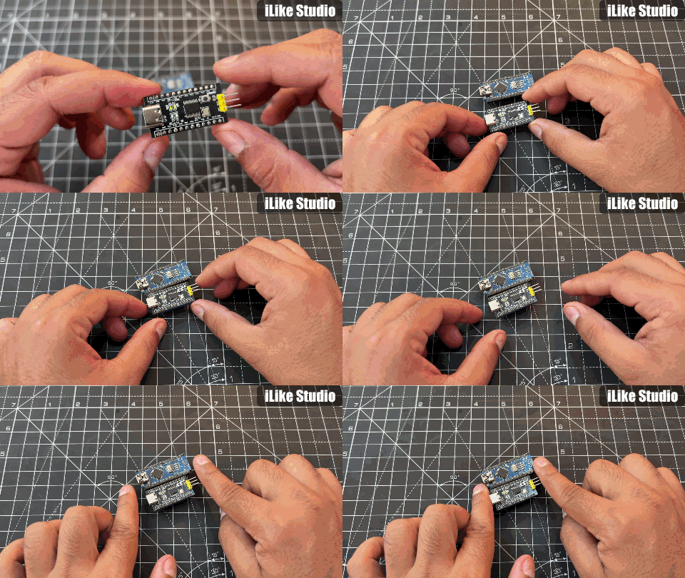
But this time I modified this version with onboard USB-to-serial, a 3.3V LDO, programming header, indicator LEDs, and all GPIOs broken out to 2.54mm headers. The idea is simple to make a minimal, low-cost, open-source development board that anyone can manufacture and assemble. The CH32V003F4P6 runs at 48MHz with 16KB of Flash and 2KB of SRAM.
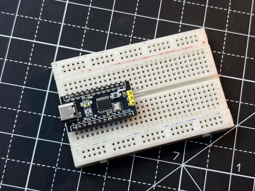
Which is more than enough for learning embedded programming, reading sensors, driving displays, and building small prototypes. In the future, I will come up with libraries which are compatible with CH32V003 like Arduino. At least the board gives a feel of instant Arduino, even though under the hood it is running a completely different architecture. In this article, I will walk you through the complete hardware design schematic, component selection, PCB layout, and the blink test code. The entire project is open-source, so you can download the design files and build your own. I have made the PCB in EasyEDA and fabricated it out using JLCPCB for just $2. I have also ordered the stencil in order to assemble a few of them for the testing purposes.
What Is the CH32V003F4P6?
The CH32V003F4P6 is a general-purpose microcontroller from WCH (Nanjing Qinheng Microelectronics) based on the QingKe RISC-V2A processor core. Unlike ARM Cortex-M based MCUs, this chip uses the open RISC-V instruction set architecture. The F4P6 variant comes in a TSSOP-20 package, which is small but still hand-solderable with a fine-tip iron. What makes this chip stand out is the price-to-performance ratio. At roughly $0.10 per unit, you get a 32-bit processor running at 48MHz that is faster than an Arduino Uno's ATmega328P. It supports I2C, SPI, USART, ADC, timers, and even an on-chip operational amplifier. Programming is done through a single-wire debug interface called SWIO on pin PD1, using WCH's WCH-LinkE programmer and the MounRiver Studio IDE. At first it may feel a little uncomfortable to program but trust me it is easy.
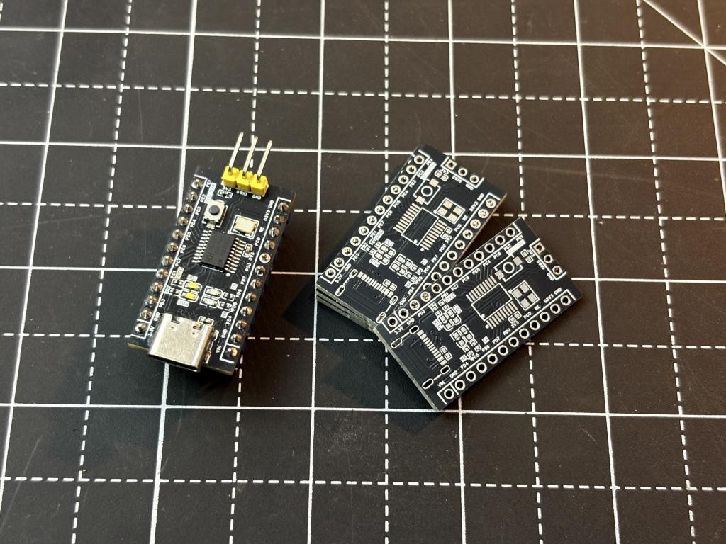
Here are the key specifications of the CH32V003F4P6:
- Core: QingKe 32-bit RISC-V2A processor
- Clock Speed: 48MHz (with internal or external oscillator)
- Flash Memory: 16KB
- SRAM: 2KB
- Package: TSSOP-20 (18 GPIO pins available)
- Operating Voltage: 3.3V to 5V
- Peripherals: 1x USART, 1x I2C, 1x SPI, 1x 10-bit ADC (8 channels), 2x Timers, 1x OPA
- Debug Interface: Single-wire SWIO (on PD1)
- Price: Approximately $0.10 per unit
Components Required
All components are sourced from LCSC and are standard parts. Here is what you need:
- 1x CH32V003F4P6 - RISC-V MCU (TSSOP-20)
- 1x CH340C - USB to TTL serial converter (SOP-16)
- 1x HT7833-A-EV - 3.3V LDO voltage regulator (SOT-89-3)
- 1x USB Type-C connector - for power and serial communication
- 1x 24MHz crystal oscillator - SMD 3.2x2.5mm package
- 6x 100nF capacitors - C0402 package (decoupling and filtering)
- 2x 1uF capacitors - C0402 package (LDO input/output)
- 6x 1k resistors - R0402 package (LED current limiting and reset pull-up)
- 2x 5.1k resistors - R0402 package (USB-C CC pull-downs)
- 4x Red LEDs - 0603 package (TX, RX, and 2 general purpose)
- 1x Tact switch - SMD 3.9x3.0mm (reset button)
- 2x 12-pin female headers - 2.54mm pitch (GPIO breakout)
- 1x 3-pin male header - 2.54mm pitch (WCH-LinkE programming)
Circuit Diagram
The board is powered through a USB Type-C connector (U4). I have used two 5.1k pull-down resistors (R4 and R7) on the CC1 and CC2 lines, which is required for USB-C to be recognized as a USB 2.0 device by the host. Without these resistors, many USB-C sources will not provide 5V. The 5V from USB goes to the HT7833-A-EV (U9) low-dropout regulator, which converts it to a clean 3.3V rail. The CH340C (U2) handles USB-to-UART conversion, so you can open a serial monitor and communicate with the CH32V003 directly over USB so no external adapter is needed. I also added TX and RX indicator LEDs (LED3 and LED4) with 1k resistors so you can visually see serial activity.
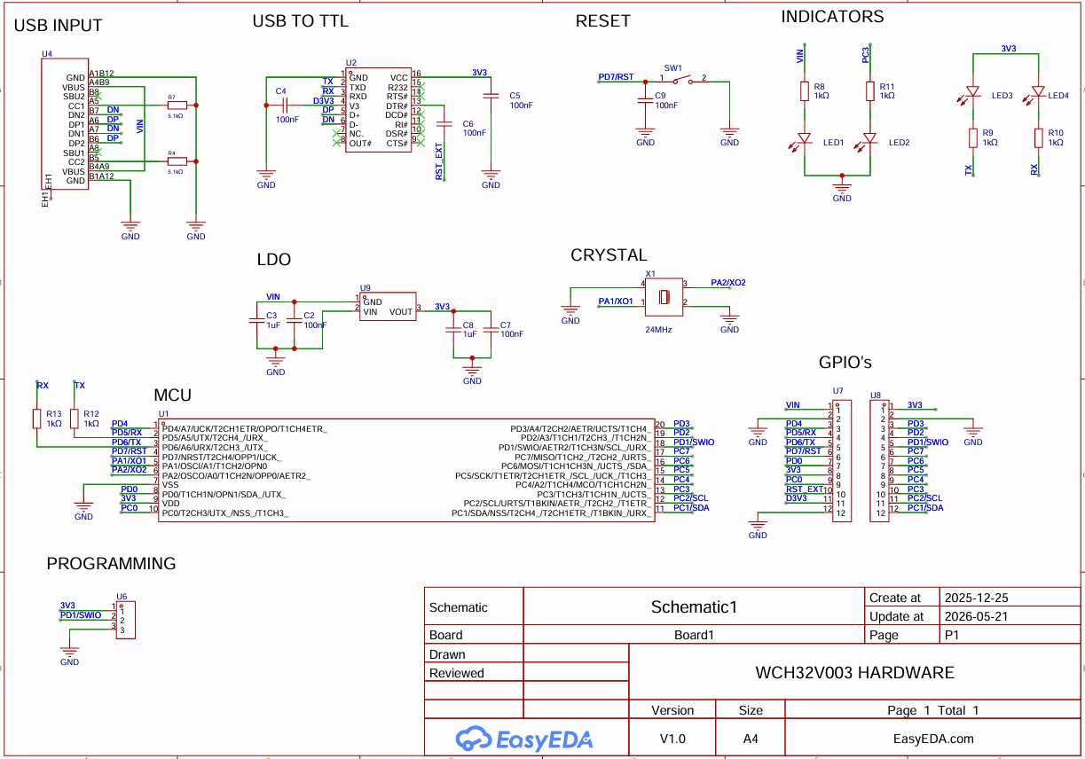
The CH32V003F4P6 (U1) sits at the heart of the board. It gets its clock from a 24MHz external crystal. The MCU internally multiplies this to reach its maximum operating frequency of 48MHz using the PLL. The reset button (SW1) is connected to PD7/NRST. I have used a 1k pull-up resistor (R12) and a 100nF debounce capacitor (C9) on the reset line. All available GPIO pins are broken out to two 12-pin female headers (U7 and U8) on either side of the board, just like an Arduino Nano. This gives you easy access to I2C (PC1/SDA, PC2/SCL), SPI, USART, ADC channels, power pins (VIN, 3V3, GND), and general-purpose I/O.
PCB Design
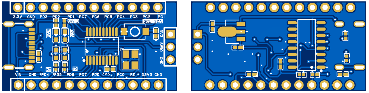
I designed the PCB in EasyEDA, keeping the board size compact to match the Arduino Nano form factor. The layout prioritizes clean power distribution in 2 layers only. Then poured the ground plane on both sides for a low-impedance ground return path. Placed the decoupling capacitors as close as possible to the power pins of both the CH32V003 and the CH340C. Crystal is placed near the MCU's oscillator pins with short, symmetric traces. The USB-C connector sits at one end with the CH340C and LDO nearby to keep signal paths short. Programming header is positioned in the end of board for easy access while the board is on a breadboard. The design files are open-source in EasyEDA format, so you can modify the layout and order PCBs from JLCPCB in just $2.
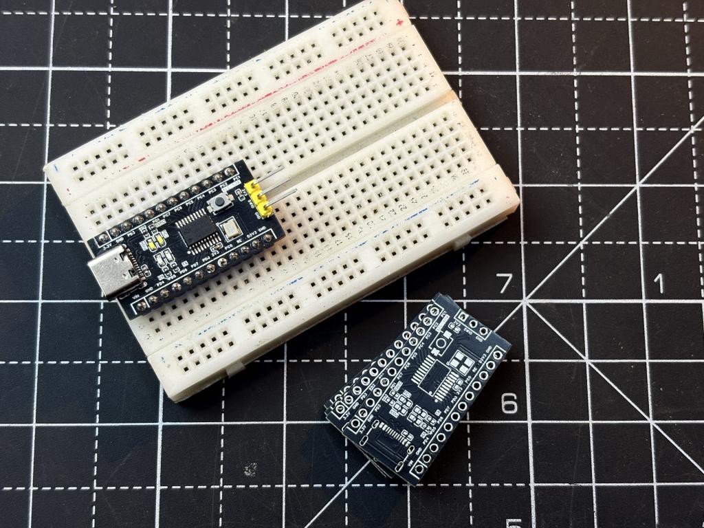
I have assembled the board myself but trust me without hotplate and proper soldering equipments like microscope and heatgun small components of 0402 size are impossible to solder. But with a skillset of soldering for 5 years I am able to solder this board myself in 2 hours. It takes a lot of solder debugging, But you can choose JLCPCB SMT assembly services to get rid of soldering by hands. All you need is a proper BOM and CPL file which is already attached within this document.
Setting Up the Development Environment
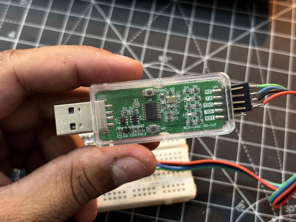
Unlike Arduino, the CH32V003 uses WCH's own toolchain. You need MounRiver Studio, which is a free Eclipse-based IDE. It comes with preconfigured RISC-V GCC compiler so no additional toolchain setup is required. You also need the WCH-LinkE programmer, which connects to the board through the 3-pin programming header (U6) with just three wires: 3V3, SWIO (PD1), and GND. Which came separately for $5, you can buy from here.
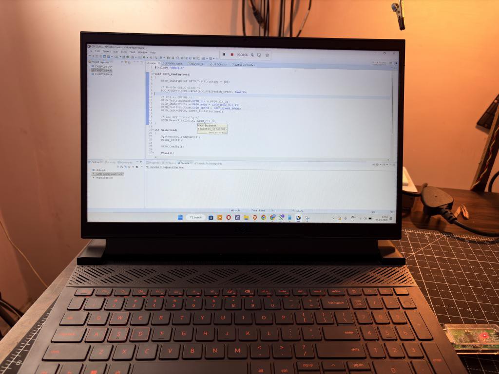
The single-wire debug interface (SWIO) is one of the unique things about WCH's RISC-V chips. Unlike SWD on ARM chips which needs two pins (SWDIO and SWCLK), SWIO uses just one pin for both data and clock. This keeps the programming header minimal and frees up more GPIO pins for your application. The workflow is straightforward you have to write code in MounRiver Studio, compile, connect the WCH-LinkE, and flash. Once flashed, disconnect the programmer and the board runs standalone from USB power. The onboard CH340C then serves as your serial monitor for debugging via USART printf.
Blink Test Code
The first thing I always do with a new board is run a blink test if the LED blinks, you know the MCU is alive, the crystal is working, and your toolchain is set up correctly. Then you can test some given examples within the attached download folder. Here is the blink code I used:
#include "debug.h"
void GPIO_Config(void)
{
GPIO_InitTypeDef GPIO_InitStructure = {0};
/ Enable GPIOC clock /
RCC_APB2PeriphClockCmd(RCC_APB2Periph_GPIOC, ENABLE);
/ PC3 as push-pull output /
GPIO_InitStructure.GPIO_Pin = GPIO_Pin_3;
GPIO_InitStructure.GPIO_Mode = GPIO_Mode_Out_PP;
GPIO_InitStructure.GPIO_Speed = GPIO_Speed_30MHz;
GPIO_Init(GPIOC, &GPIO_InitStructure);
/ LED OFF initially /
GPIO_ResetBits(GPIOC, GPIO_Pin_3);
}
int main(void)
{
SystemCoreClockUpdate();
Delay_Init();
GPIO_Config();
while(1)
{
GPIO_SetBits(GPIOC, GPIO_Pin_3);   // LED ON
Delay_Ms(500);
GPIO_ResetBits(GPIOC, GPIO_Pin_3); // LED OFF
Delay_Ms(500);
}
}
First we have to initialize the structure of GPIOs and USART by default, then the main() function initializes the system clock and delay timer, calls our GPIO configuration.
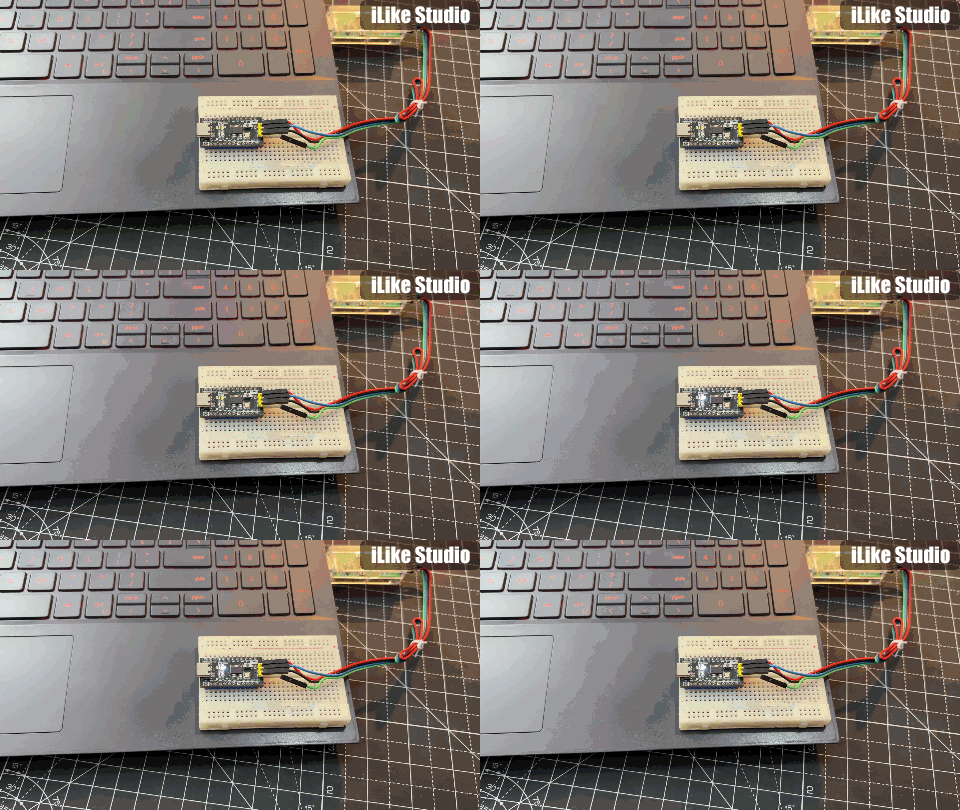
This work same as void setup and void loop in Arduino. Looping enters an infinite loop that toggles the LED every 500 milliseconds. The code structure follows WCH's standard peripheral library pattern, similar to the STM32 Standard Peripheral Library. The `debug.h` header includes all necessary peripheral definitions and delay functions.
Practical Notes and Tips
Here are some things I learned while building and testing this board. The HT7833 LDO does a good job, but USB power can be noisy depending on your computer or charger for ADC measurements, consider adding extra filtering on the analog lines or use battery power for cleaner results.
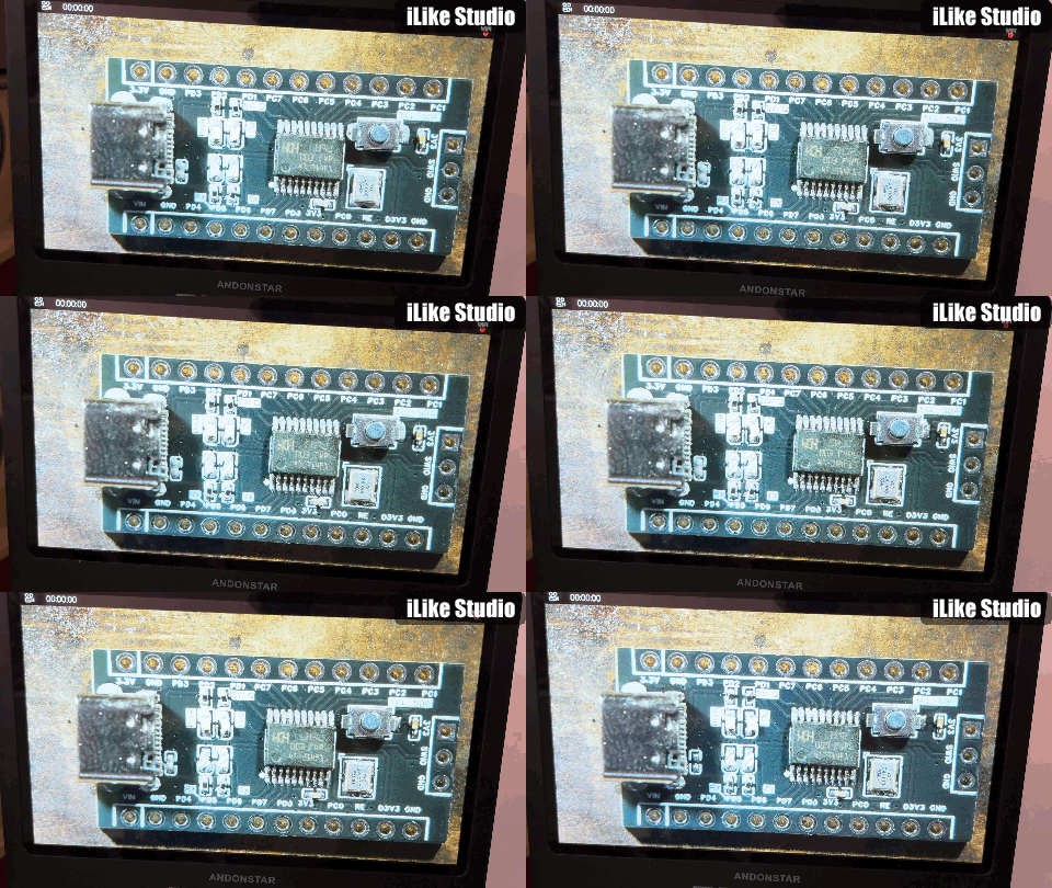
The CH32V003 in TSSOP-20 is manageable with a fine-tip soldering iron and flux, but I recommend solder paste and a hot air station if you have one, it makes the 0402 passives much easier too. If the WCH-LinkE cannot detect the chip, double-check your 3V3 and GND connections on the programming header and keep the wires short, since SWIO is sensitive to signal integrity. For serial debugging, just open a terminal at 115200 baud and the onboard CH340C handles the rest.
Outro:
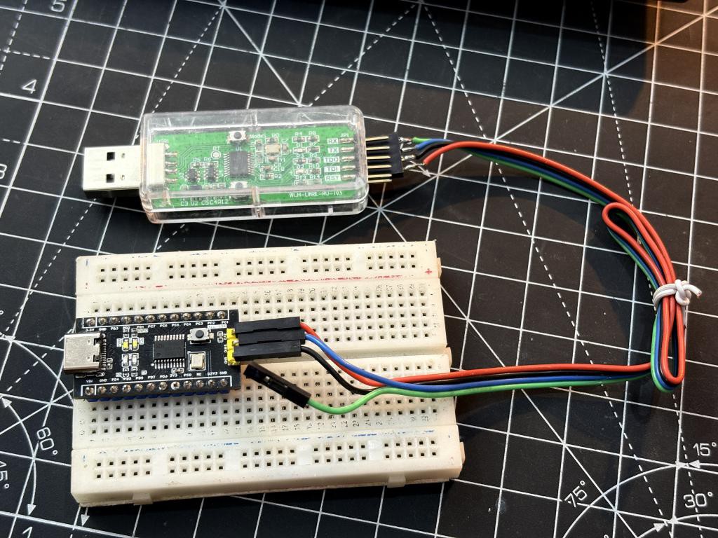
This CH32V003F4P6 development board has been a really satisfying project to design, build, and test. You get a fully-featured 32-bit RISC-V MCU for ten cents. And now wrapped in an Arduino Nano form factor with onboard USB-to-serial, LDO, programming header, and indicator LEDs. This board is a practical tool for both learning and prototyping. The entire project is open-source with EasyEDA design files, BOM with LCSC part numbers, and over 20 example projects. You can manufacture this board yourself, modify the design, or just use the example code to learn RISC-V embedded programming. In future I will continue this series with some really cool programming stuff. If you have any questions or suggestions, please comment below. I would love to see your builds!