 gamadril.dev
The device I'm working on is an aftermarket LCD device with CarPlay and Android Auto support. There are a lot of them with different screens, additional cameras, other features depending on the price and each of them has its own name. I took the cheapest one with 7-inch LCD with no extra features based on an Allwinner F133/D1s CPU, 64 MB RAM , 16 MB flash and running Melis RTOS. Typical UI:
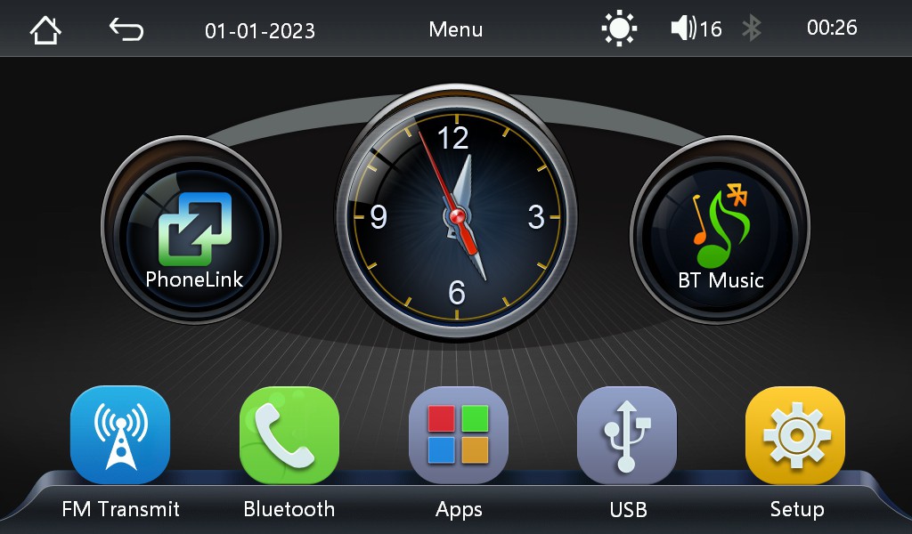
There are other devices which might look the same but are based on ARM CPUs - for those devices the tools used here are not helpful, but my work might give you an idea how to do the same. Maybe if I get such a device in my hands, I will also try to RE it...
Of course when I got the device the first thing I did was opening it and looking inside - because like Tim always says - it might need "more power"! The final target is to add CAN bus support to it and extend with custom UI screen to show vehicle data - either by patching the existing UI engine or replacing it completely with custom UI including own (Linux) kernel. The big challenge is to keep the CarPlay and AA functionality working.
If you wonder why there are pictures of two boards - my first device never made it into my car. After 2 weeks "hacking" the disassembled device on my table I realized that this is now a "dev board" and ordered another similar-looking device from another seller with same specs. I hoped it might give me more options for analyzing, but at the end the second device had same software and same board, but one revision lower.
The LCD is labeled as JC I07-031/B018AB12-1HD01. I could not find any info about it, but for sure it's a parallel LCD with gt968 I2C touch screen controller. Although there are no detailed specs for the LCD, the extracted sys_config.fex file provides enough information (like resolution 1024x600) about it's wiring and timings.
The first step in the firmware analysis is to get this firmware for analysis. I asked both sellers I got my devices from for firmware updates or recovery files but as expected got nothing. So dumping the flash was the only way to access the firmware. 16MB SPI NOR flash is not protected and easy to read out with common tools, however after digging deeper into the datasheets of F133/D1s CPU I was sure there must be a way to do it over USB and ideally without opening and modifying the device at all...
The USB-A port on the side of the device is an OTG USB port and can act as host and device. If the CPU does not find any bootable media, it will switch to FEL (Firmware Exchange Launch) mode and when connected to the development machine using a USB-A to USB-A cable will be detected as "
ID 1f3a:efe8 Allwinner Technology sunxi SoC OTG connector in FEL/flashing mode". With the xfel tool it is then possible to access the flash.
When I started reverse engineering that device I used a simple method to enter FEL - connecting MOSI flash pin to GND (that's why there is a button on the picture) so no boot media is found and FEL is entered automatically. Later I found out that SD card has a higher boot priority - makes sense to be able updating firmware from the SD card. Using a small boot image from the SD card makes it possible to enter FEL mode much easier without opening the device. Details about it are in the GitHub repository.
So after getting the full flash dump the next step was to analyze it using tools like binwalk, strings etc. For the analysis I found repositories on GitHub containing projects related to the D1s and parts of the Melis RTOS source code including the C tools used to generate images out of compiled binaries.
Final analysis result of the dump is a combination of bootloaders and partitions - something we can work with.
Based on the flash dump we have this map
| Image File | Offset | Size (Bytes) | Format | Description / Role |
|---|---|---|---|---|
| boot0.bin | 0x00000000 | 49152 | eGON.BT0 | Bootloader (SPL) |
| gpt.bin | 0x0000c000 | Variable | GPT Partition Table | Preamble (0_ppt.bin) + partitions 1_bootA, 2_ROOTFS, 3_UDISK |
| 0_ppt.bin | Inside GPT | 1024 | GPT preamble | GPT preamble (LBA 0–1): protective MBR + primary GPT header - not a data partition |
| 1_bootA.bin | Inside GPT | Variable | TOC1 / sunxi-package | Contains Melis RTOS kernel & config |
| 2_ROOTFS.bin | Inside GPT | 14614528 | MinFS | Allwinner proprietary filesystem (modules, apps, configurations) |
| 3_UDISK.bin | Inside GPT | 917504 | FAT16 | User disk partition containing resources and config scripts |
If you are interested in the boot process in details, Yury did a great job describing it here: D1 boot process
To work with the flash dump directly and have all tools in one place - the toolbox "d1s-melis-tools" was born. The main reason for doing it was to avoid the pain of collecting different tools from different sources for each single step and for which also different operating systems are necessary and having a long tutorial for myself at the end how to get them all working together. And after updating own Linux distribution some shared libraries might not match any more...
Tools are written in Rust to keep the Rust skills up-to-date and because Rust is cool!
The included tools are:
- dump_tool - extracts relevant parts out of the flash dump and pack them back together
- gpt - partition slicer and merger
- melis-boot - extracts data out of the bootA bootloader - uncompressed Melis kernel, hardware config file and pin mapping. Also packs everything back.
- minfs - ROOTFS extracting and packaging tool - extracts files including restoring correct ELF file headers and pack them back together
- udisk - FAT16 packer/unpacker - just for completeness. That partition can be actually mounted directly on the dev machine.
- xfel_spi_nor - small part of the xfel tool reimplemented in Rust, only with SPI NOR support - also just to have everything in one place.
- sd_fel_switcher - small payload to put on SD card for booting into FEL mode
My first "hack" was to change the boot image. Replacing the original JPEG image with my own in ROOTFS, repacking the dump and writing it back in FEL mode indeed worked. However after poking inside the binaries with Ghidra the "official" way to change the start image was discovered. If you landed here because of it, check the instructions at the end.
So the test showed that using FEL mode it's possible to have RW access to the flash very easy and this is also the way to "unbrick" your device - just keep the original flash dump in a safe place for later.
So with the tools in place, it's now possible to modify the firmware.
To test the realistic possibility of creating and running own software on the device in the case the modifications of the existing software would lead to no result or would be too complicated I tried to get DOOM running on it. Of course one can start from scratch and do it the bare-metal way - which is fine if you want to train your skills in writing own OS. I didn't want to reinvent the wheel and write own OS and looked around for existing options. The most usable are: Melis RTOS v4.0 as the original firmware based on, Tina-Linux or RT-Thread (Melis RTOS is based on RT-Thread kernel). I thought RT-Thread should be enough as base for DOOM execution, so I used it together with doomgeneric which makes the process of porting DOOM easier. However bringing it to a playable state was not easy. Although RT-Thread supports the D1s, its state is outdated relative to the master. Older release-branches do not compile with current tools and without help of AI I would spend hours fixing it, applying LCD and TS settings of the device and tweaking rendering path to acceptable FPS values. In the end, DOOM screen was rendered, however unplayable slow. Several hours later tweaking the framebuffer rendering and using hardware upscaler the game was running acceptable. The "official way" of testing compiled output I found in every official tutorial is making a complete image out of it and flash to SD card. Of course this is a completely unusable option, if you code, build, deploy, debug in the loop. So the better way is to load everything to RAM and execute directly from there - some "glue" generated by AI around the parts was necessary to get everything running that way.
I always wanted to say "I ported doom to XXX", in this case it was D1s, but actually I found other doom ports on GitHub for D1s (Yury did it the bare-metal way) and without AI help my port would probably never work. But the only reason for it was to get the feeling for the development round-trip on that platform and that helped a lot.
So back to the extracted parts from the firmware.
- boot0.bin is not of much interest for firmware modifications. Its primary task is to complete basic hardware initialization and load the rest of the system - typical tasks of a bootloader.
- gpt.bin holds the partition table of other system parts.
- bootA.bin includes extended hardware configuration and the Melis RTOS kernel with drivers. The decompressed kernel is of more interest because it contains initialization and control code for the Wi-Fi and Bluetooth modules used for Android Auto and CarPlay communication. It also communicates with the MFi (Made for iPhone/iPad/iPod) IC necessary for the CarPlay connections. Patching the kernel in its binary form is not easy, replacing it with own build might be possible if the mentioned functionality can be disassembled and re-implemented. Driver code for the SV6256 Wi-Fi module is available and can be implemented, other parts might require more effort. Another IC with PCB antenna near it has the marking "CHXC14B5B" and seem to be AB5301B from bluetrum (14B5 as HEX -> 5301 as DEC) - might be used for direct Bluetooth music streaming. But let's assume the kernel does its job and does not needs any patching for now. So the next firmware part is most interesting to modify.
- ROOTFS.bin is the read-only partition containing the UI and modules used by the UI e.g. implementing AA/CarPlay layer. Modules/executables are normal ELF binaries, so can be disassembled and in theory cross compiled on dev machine and replaced. UI interface is completely proprietary and requires much guessing and reverse engineering how the screens (.data files) are defined - they seem to be declarative with references to functions in the main UI module (apps/init.axf). Here are also two ways to go - extending with own code after understanding how UI works or replacing completely with own implementation - again after understanding how AA/CarPlay is integrated...
- UDISK.bin is a writable partition used as the primary NVM storage for settings.
That's all for now. More information will follow after I spend some time poking around inside the UI and its modules.
Some useful info as a side note. In the Settings menu, Factory settings entry asks for a 6-digit code. Each code opens a different hidden configuration screen.
Source: Passwords are defined in 2_ROOTFS.bin.out/apps/init.axf (main shell / login UI). Password checks are hardcoded strings plus two values from apps/Config.ini (also on UDISK).
| Code | Menu (English) | Config / Notes |
|---|---|---|
| 112233 | Logo settings | logoPassword in [CONFIG] (default in firmware) → SetupLogo.data |
| 113266 | Factory settings | factoryPaswword in [CONFIG] (typo in stock INI) → SetupFactory.data |
| 112345 | Debug mode | Hardcoded → SetupDebug.data |
| 001106 | Factory settings (extended) | Hardcoded; menu id 25 (separate code path from 113266) |
| 230762 | Interface selection | Hardcoded; UI style / layout picker (uiType / uiID area) |
| 123579 | Self-check | Hardcoded; minimal UI (empty on my device) |
Other digit strings exist in init.axf (WiFi defaults, version blobs, etc.) but are not wired into this login dispatcher.
"Debug mode" menu is quite interesting, because it contains the "USB mode" switch.
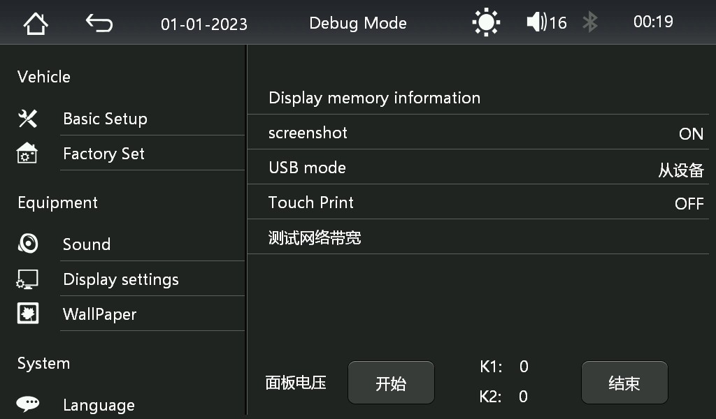
Clicking on it switches the device from host to device mode and is shown as "
ID 0525:a4a1 Netchip Technology, Inc. Linux-USB Ethernet Gadget". As the name says it should be a network device, however I could not find any way to communicate with it. Wireshark does not show any packets coming from the device either. If you have an idea - write a comment.
Activated "screenshot" entry will save at fixed time rate screenshots to inserted SD card into "ScreenShot" folder - the way screenshots of UI here were done.
The "Factory Settings" menu contains the possibility to export current config (Config.ini) to SD card and import it back - another (easier) way to make config changes (app changes, hardware config is still packed inside boot0) without touching the flash dump.
How-To: Change Startup Logo
If you only want to change the boot-up logo **without modifying the firmware**:
1. Format a SD card as FAT32
2. Create a `Logo` directory on the card
3. Copy your JPEG image to `Logo/`
4. Insert the SD card into the device
5. Enter factory settings using code `112233`
6. Click "Internal card" text to switch to "External card"
7. Select your image to set it as the boot logo
8. Exit the menu — the image will be copied to UDISK as `stalogo.jpg`
9. Remove the SD card and reboot