 Jaime Clot

The Project Story
A personal project of mine. I have always been fascinated by retro-computing and low-level hardware architecture, especially the Intel MCS-4 system. However, modern emulators often rely on high-level abstractions that hide the actual constraints of the era.
Quadium 4004 Workbench is a Windows desktop laboratory designed to learn and experiment with a complete, hardware-faithful system. It is centered on the Intel 4004 CPU but models everything: ROM, RAM, shift registers, inter-chip bus, and peripherals.
Core Features & Architecture
- Pure Hardware Topology: Replicates the 4004, 4001, 4002, 4003, and the raw bus semantics aimed at the historic machine.
- Wired-OR I/O: Multiple virtual peripherals connected to the same port combine exactly like an electrical OR bus.
- QuadBasic Transpiler: A 4-bit BASIC implemented directly in the UI that transpiles to native Intel 4004 assembly. To keep it technically accurate to the original hardware, it lacks modern "magic" like strings or dynamic arrays.
- Real Debugging: Hardware breakpoints by PC, single-step execution, pause, and full RAM/ROM state inspection.
- Lab Workflow: Assemble, program the virtual ROM, run, and track the loaded image with a live disassembly view.
- Visual Layer: An integrated VDP-style 64x48 virtual display processor inspired by the classic TMS9918.
- Speed Control: Adjustable execution speed (IPS) from classroom-slow up to real MCS-4 hardware rates to stress-test runs.
- Machine Snapshots: Save and restore the full state of the CPU, memory, ports, 4003, and bus at any cycle.
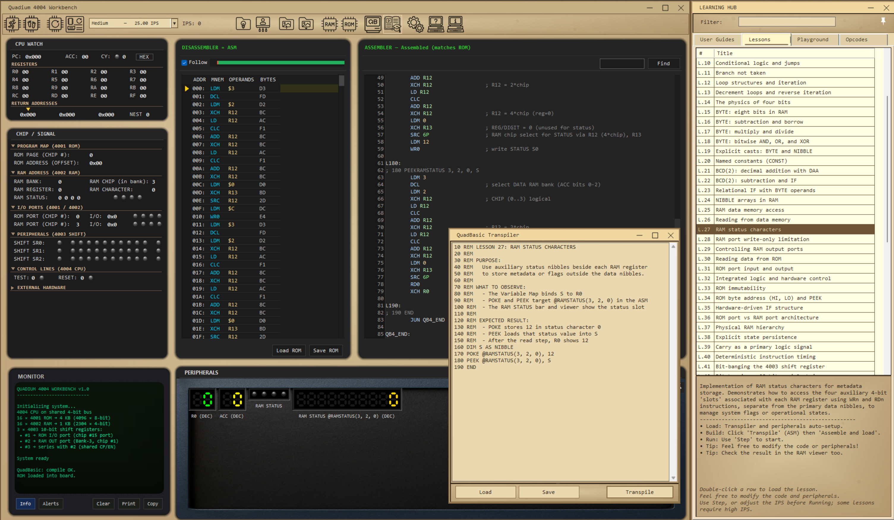
From High-Level to 4-Bit Reality: Code Transpilation to understand how the QuadBasic transpiler bridges the gap between readable code and raw Intel 4004 constraints, here is a practical compilation example. When you write a single string statement to target the display, the workbench generates the historical MCS-4 assembly architecture, populates the variable maps, maps the CPU registers, and setups the page-F runtime stubs dynamically.
The Source Input
10 PRINT @SCREEN, "Hi hackaday.io"
20 END
The Transpiled Intel 4004 Assembly (Raw Output)
; ===== Basic4 mini-BASIC => 4004 ASM =====
; R0..R9   : user NIBBLE variables (see Variable Map).
; R10 (T0) : expression temp, logic operand A, JMS results.
; R11 (T1) : expression temp, logic operand B, print char HI.
; R12 (ADR): FIM/SRC address (4*chip+reg); decimal quotient.
; R13 (DIG): FIM digit; print-started flag; PRINTDEC scratch.
; R14 (WLO): wide scalar low nibble (BYTE).
; R15 (WHI): wide scalar high nibble (BYTE).
; BYTE lives in RAM; R14/R15 are a per-statement window.
; System RAM: RAM[3,3,2,*] and RAM[3,3,3,*] (compiler/runtime scratch). Carry @ [3,3,3,0].

; =====================================================================
; BASIC4 VARIABLE MAP
; =====================================================================
; #   Name       Type          Storage
; --- ---------- ------------- ------------------------------------------
; --- ---------- ------------- ------------------------------------------
; Registers used: none of R0..R9            (10 free)
; RAM used:       0 nibbles
; =====================================================================

        ORG 0000H
; --- INIT OUTPUT DEVICE @SCREEN ---
        LDM 0                   ; 0=SCREEN
        JMS B4_SETDEV

L10:
; --- SELECT OUTPUT DEVICE (RAM[3,3,3,13]) ---
        LDM 0
        JMS B4_SETDEV

; 10 PRINT @SCREEN, "Hi hackaday.io"
;   char 'H' = 72 (0x48)
        LDM 8
        XCH R10
        LDM 4
        XCH R11
        JMS B4_PRINTCHAR
;   char 'i' = 105 (0x69)
        LDM 9
        XCH R10
        LDM 6
        XCH R11
        JMS B4_PRINTCHAR
;   char ' ' = 32 (0x20)
        LDM 0
        XCH R10
        LDM 2
        XCH R11
        JMS B4_PRINTCHAR
;   char 'h' = 104 (0x68)
        LDM 8
        XCH R10
        LDM 6
        XCH R11
        JMS B4_PRINTCHAR
;   char 'a' = 97 (0x61)
        LDM 1
        XCH R10
        LDM 6
        XCH R11
        JMS B4_PRINTCHAR
;   char 'c' = 99 (0x63)
        LDM 3
        XCH R10
        LDM 6
        XCH R11
        JMS B4_PRINTCHAR
;   char 'k' = 107 (0x6B)
        LDM 11
        XCH R10
        LDM 6
        XCH R11
        JMS B4_PRINTCHAR
;   char 'a' = 97 (0x61)
        LDM 1
        XCH R10
        LDM 6
        XCH R11
        JMS B4_PRINTCHAR
;   char 'd' = 100 (0x64...
Read more »
 zpekic
 gbm
gbm
 David Hunter