 Mingjie Li
Required Components
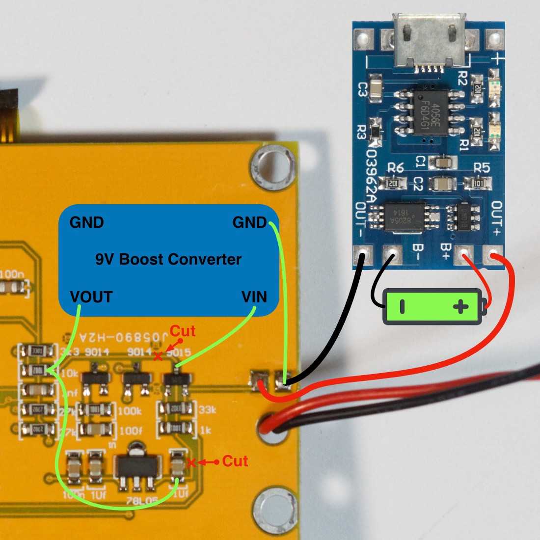
- TP4056 lithium charger module with protection circuit
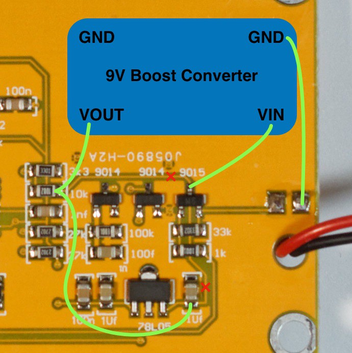
- A boost converter module capable of producing 9V output from a single lithium cell (e.g. MT3608 or TPS63070 boost converter module)
- A single-cell lithium-ion or lithium-polymer battery
- Wire and solder
Drawback: No Lithium Battery Voltage Monitoring
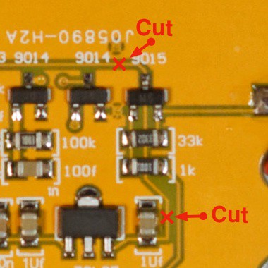
The voltage display will always show the regulated boost converter output near 9V, so there is no way to monitor the actual lithium cell charge level. Connecting the voltage detection point directly to the lithium cell was attempted, but the tester has a minimum voltage threshold for startup and will refuse to boot at lithium cell voltages, making this approach unworkable. The TP4056's protection circuit handles undervoltage by cutting power at the cutoff threshold. The only indication of a depleted battery is that the tester simply won't turn on.


 Manuel Tosone
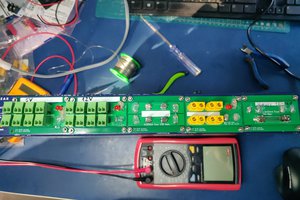
 Enki
Enki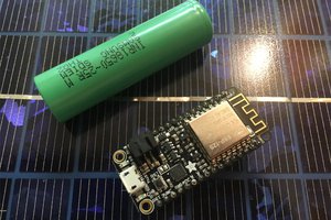
 Justin Maynard
 Lithium ION
Won't it be better to choose a lower voltage for the boost converter?
As it's followed by the linear regulator U1, I'd choose the lowest output voltage that provides enough margin for U1 to work, maybe around 6.5-7V (you'll need an adjustable one).
Another (maybe better) possibility is using a 5V boost converter, connecting its output to the output of U1 (if the noise in the output of the boost converter is low enough, so the filtering effect of the linear regulator isn't needed)