 Edward Viaene
A few things I've been doing since the last project log:
- Writing firmware to test all components
- Decided not to use PIO after all, the MCU will only orchestrate, the dataplane will be the iCE40 (FPGA)
- When not using PIO, there's no need for the RP2350B anymore; most likely, I will switch to STM32H563VIT6 so that I have MAC support. It's actually less expensive to use the STM32 without an external flash, oscillator, inductor, or MAC chip. It’s actually close price-wise, but the RP2350B is short on SPIs if you need Ethernet. Too bad, because I liked the dual-core (didn’t use it yet, though) and PIO (FPGA replaced PIO for my use case).
- Did lots of FPGA test cases. The iCE40 is really nice to work with when it suits your use case.
- Didn’t have much time to test the analog path yet, but spend instead a lot of time on v2, which will have a calibration path (DAC to ADC), higher precision (14 or 16 bits), and higher voltage support (the ADC will have a 12:1 attenuator, so we can take -+ 30V in and DAC will be have a 3V3, 5V and +-12V path)
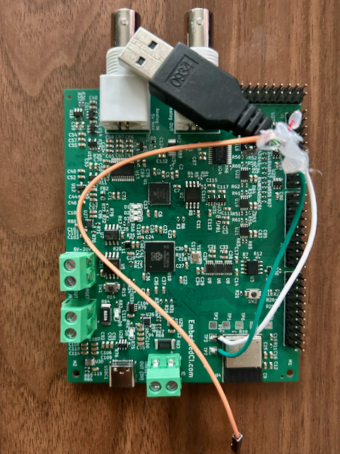
- Also had to use a heat station to put the ESP32 in place, as JLC didn’t put it (the component would put me out of PCB Assembly economy, so I opted to do it myself after the board was validated enough). I was hoping for castellations on the chip, but I took the version with pads unknowingly at the bottom instead of on the side. It’s a bit trickier, and although the ESP32 gets its voltage, I can’t reach it over UART/USB. I’m also missing a pull-up on a pin, but most likely I'm accidentally shorting the EN port (that's what the continuity test shows), and it needs a reflow.
- Working now on some pytest cases to flash a target device, use eFuses to manage power, check UART, launch sensor simulation over i2c, enable on-board pull-ups, and see if the firmware of the target device can see the sensor. The UART, I2C, and SWD are all done in the FPGA with the iCE40. Here’s a snippet of the Python test code:
# Flash → emulate BMP280 → power cycle → assert UART in one test

import re
import pytest
from embeddedci import benchpod as bp

APP_OK  = re.compile(r"APP_OK")
PRESENT = re.compile(r"chip id match=0x58|bmp280_detected=yes")


@pytest.mark.hardware
def test_bmp280_sensor_present(benchpod, pins, firmware):
    """Flash DUT, emulate BMP280 on I2C, power cycle, assert on UART."""

    # 1. Flash
    result = benchpod.flash(
        file=firmware,
        target="target/stm32f4x.cfg",
        swclk=pins.swclk, swdio=pins.swdio,
        nreset=pins.nreset, target_power=pins.efuse,
        verify=False,
    )
    assert result.ok

    # 2. Emulate BMP280 on I2C
    #    I2C is open-drain; enable pull-ups so the bus idles high.
    benchpod.enable_pullup(pins.i2c_sda, pins.i2c_scl)
    benchpod.enable_i2c_sensor(
        bp.Sensor.BMP280,
        sda=pins.i2c_sda, scl=pins.i2c_scl,
        address=bp.BMP280_ADDR_PRIMARY,
        temperature_c=22.5, pressure_pa=101000,
    )

    # 3. Power cycle + capture UART
    cap = benchpod.power_cycle_and_capture(
        rx=pins.uart_rx, tx=pins.uart_tx, efuse=pins.efuse,
        delay=1.5, duration=6.0, until=PRESENT,
    )

    # 4. Assert
    assert cap.match(APP_OK),   f"no APP_OK banner:\n{cap.text}"
    assert cap.match(PRESENT), f"BMP280 not detected:\n{cap.text}"
    assert benchpod.i2c_sensor_status().get("transactions", 0) > 0
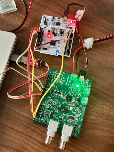
Here's the test running:
Also, here’s a picture of the ESP32 test pads with the USB data ports. Connected it to a USB cable to see if I could see anything, but as said earlier, it’s most likely a reflow issue. Still, I found it interesting that you can just solder a USB cable to the data ports.
Discussions
Become a Hackaday.io Member
Create an account to leave a comment. Already have an account? Log In.