 Edward Viaene
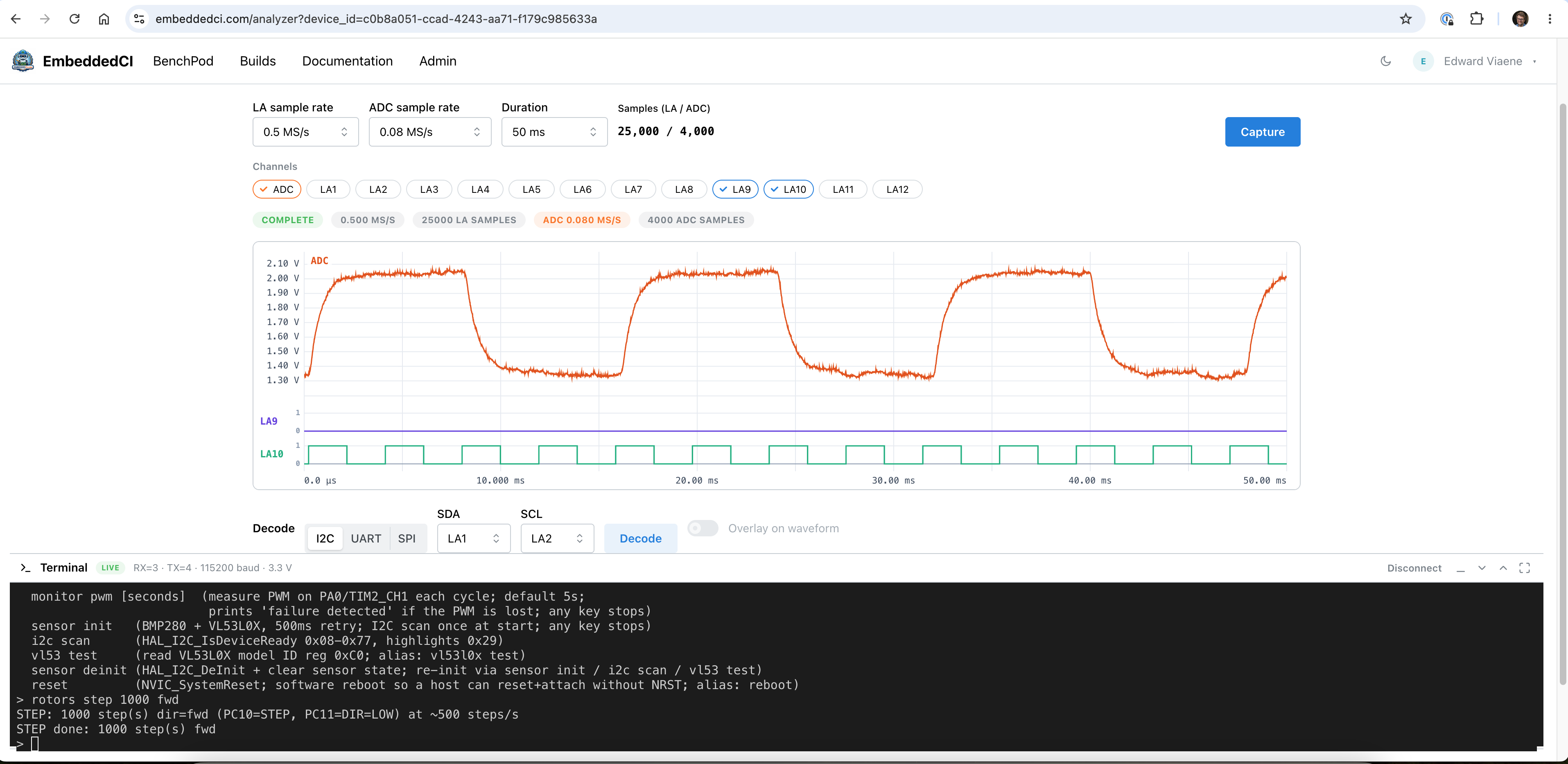
The goal: show digital and analog in a single view.
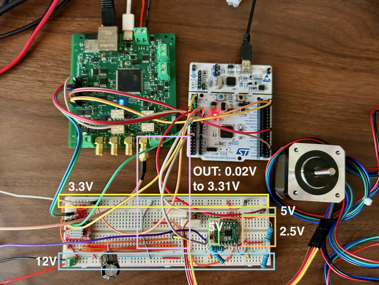
The test: to show how to verify stepper motor timing on a Device Under Test (an STM32F446RE). Logic and analog are sampled off the same clock (using an iCE40 FPGA on the BenchPod).
We have a 48MHz oscillator on the board. Unfortunately, I didn't get all the code running at 48 MHz immediately, so we're split between 24 MHz and 48 MHz in the deployed ICE40 code. Mainly, the SPI interface for receiving commands would need a serious rewrite if we wanted to run that at 48Mhz, and it doesn't need to, so those parts are running at 24Mhz.
There are 14 Logic Analyzer pins available to either output timing or to use for a specific protocol, such as UART. This is all at runtime, so you can say pin 3 and 4 are now RX and TX for UART, and I want to see the output on pins 9 & 10, because that's where I have my step direction and step input connected.
To monitor the current of the coils (or 1 coil in this example), we use a shunt resistor and an INA282 to amplify the analog signal. That way, we can see the analog data from the coil and match it with our digital signal from the step motor.
The captured data is written over quad SPI to the PSRAM, where the STM32 can read it. The iCE40 is driving a signal on a pin for the STM32 to read, to ensure they're not both talking to the PSRAM at the same time, so the STM32 has to wait until the writes are complete. The data is then sent from the stm32 to the dashboard via a WebSocket over Ethernet. As described earlier in the previous log, we're using lwIP for all this.
Discussions
Become a Hackaday.io Member
Create an account to leave a comment. Already have an account? Log In.