 shlonkin
Hardware - Keep in mind that this is not the main part of the project. It is simply an easy to make testing device for the software. Everyone and their cousin has built a little plotter out of optical drive mechanisms, so it's nothing too exciting. On the other hand, it might inspire other beginner tinkerers to make something fun using parts from their junk pile.
Sorry, I didn't take many progress pictures, but it is pretty easy to figure out just by looking at it.
Here's a brief overview.
- The two metal mechanisms were taken from junk DVD drives. Don't bother with CD drives as they just have geared DC motors rather than steppers.
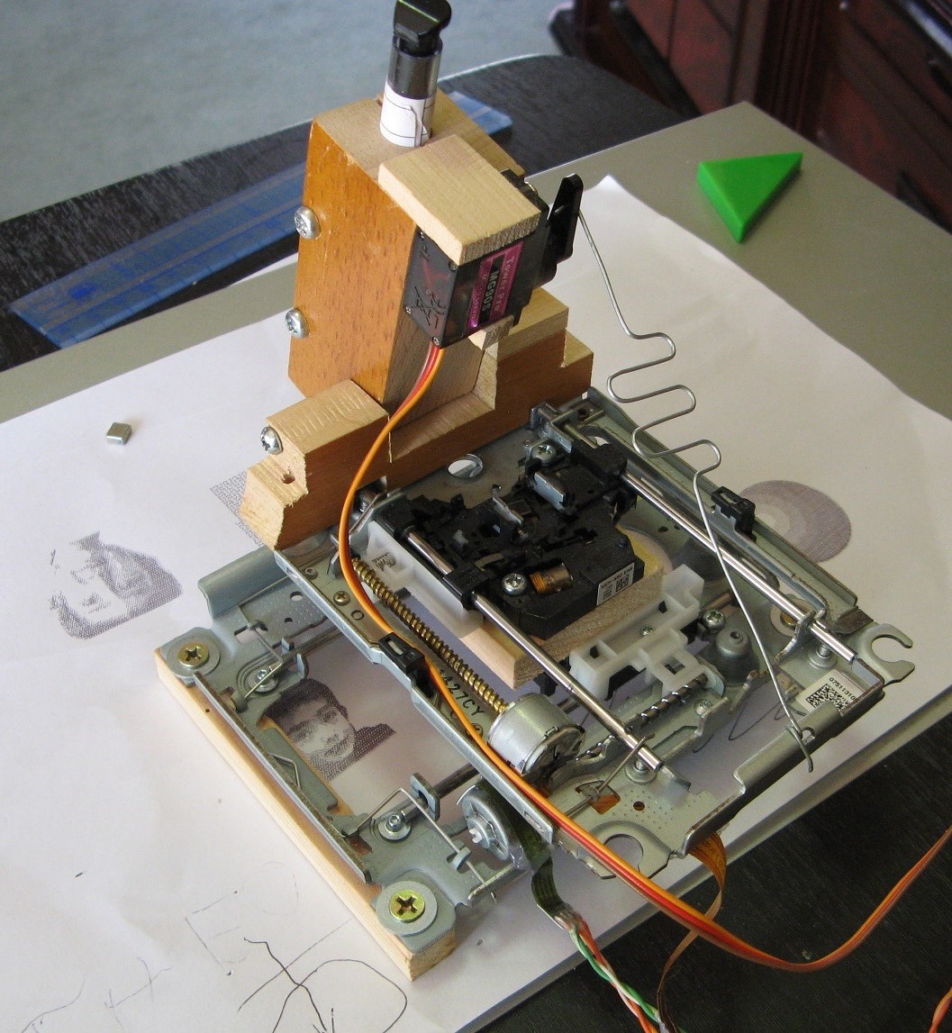
- A chunk of wood was screwed to the plastic optics carriage on on drive. The second was placed perpendicular to the first and its carriage was then screwed to the wood as well. It should be as precisely perpendicular as possible.
- Some scrap wood was cut into a hinge shape and attached to the upper drive. A pen is inserted through a hole in the moving piece of wood.
- A servo is attached to the wood and a piece of steel wire runs from the actuating arm to the upper drive's frame.
- The wire is bent into a simple spring to keep a light pressure between pen and paper.
- To keep it securely in place, strong magnets are attached to the base and it sits on a steel surface. This holds the paper and the machine securely, but can simply be lifted up to move the paper.
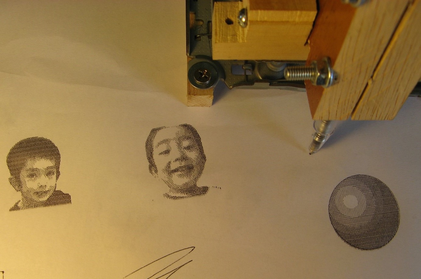
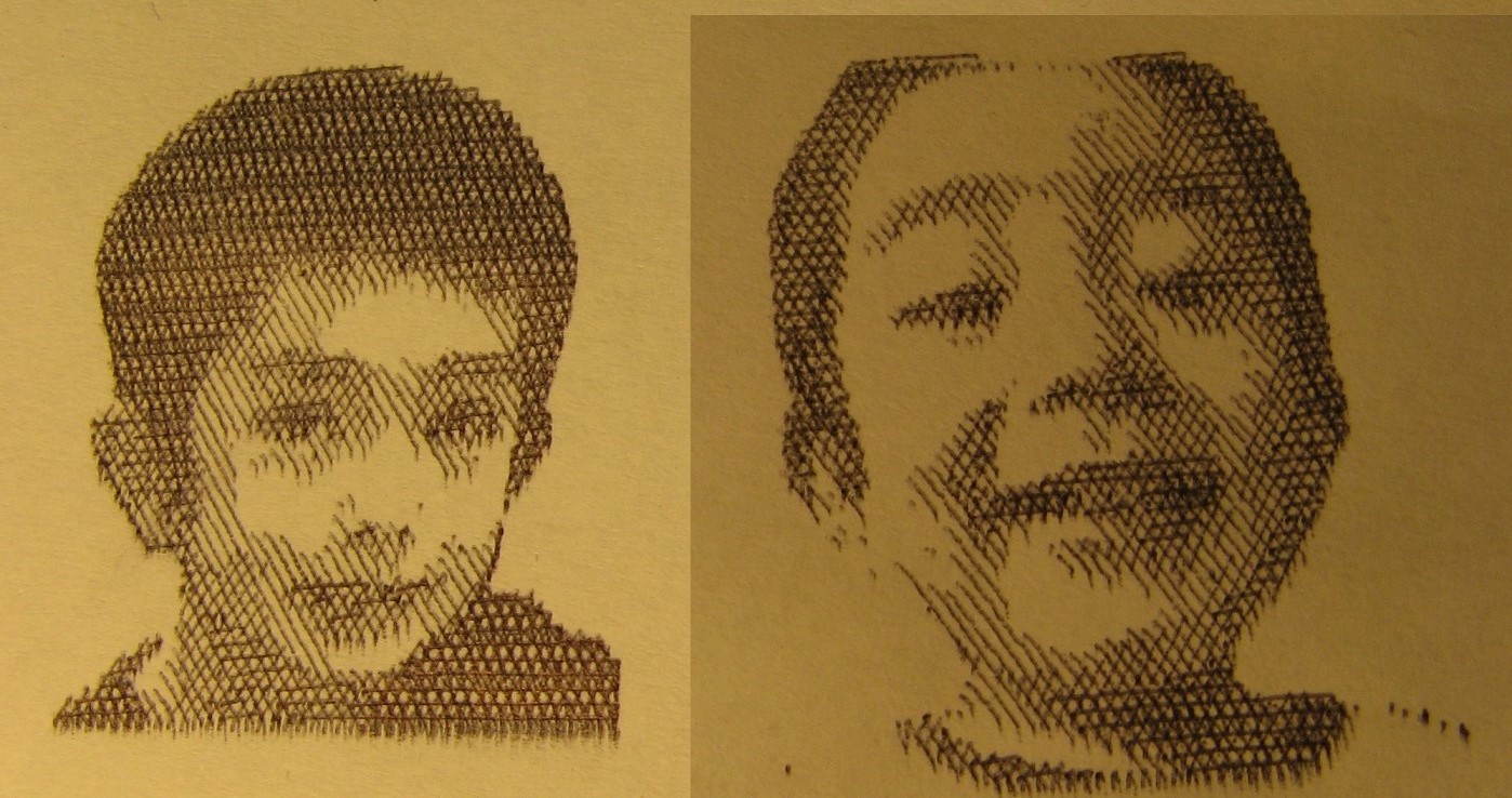
Tests - As you can see above, I have drawn several pictures using the crosshatching software, which by the way is the main portion of this whole project and is still in early development.
Anyway, these pictures are all about 3x3cm which is really very small. Despite the tiny size in relation to the pen stroke resolution, I was able to get some really clear images with fine detail. I am happy. Oh, and these were made using four hatch levels/angles.
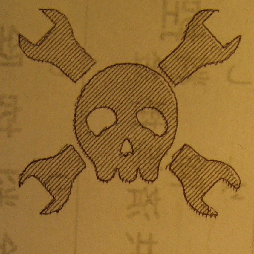
And to show the ability to draw both vector paths(from SVG files) as well as shading, here is your favorite logo. By the way, that writing you see was just something printed on the other side of the paper.
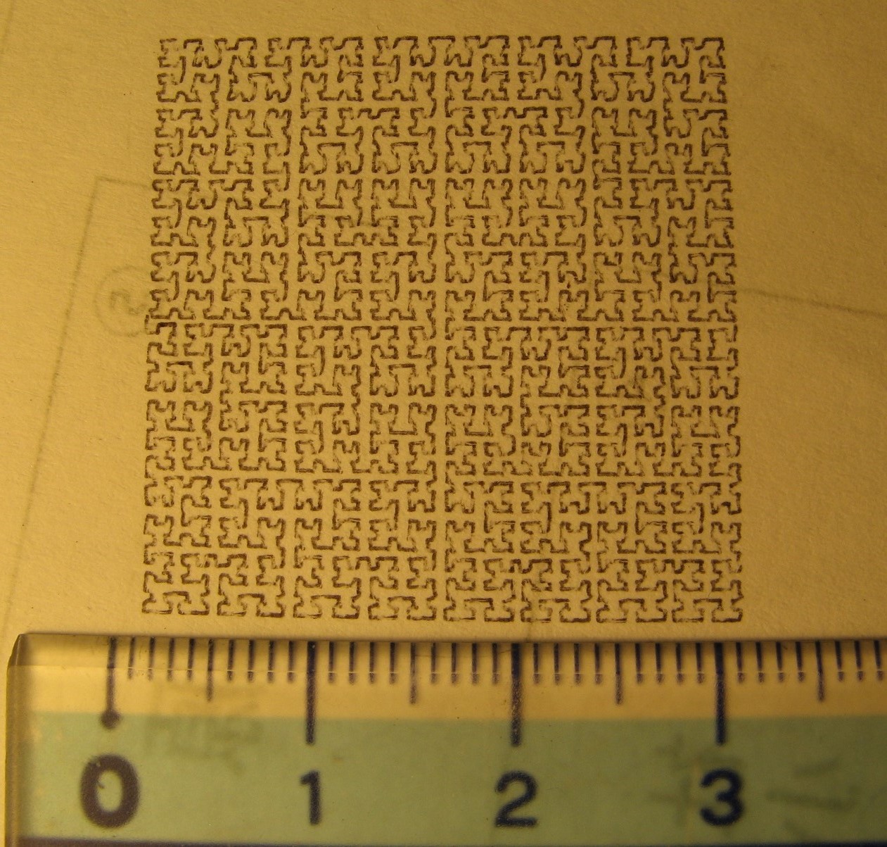
And while I'm at it, I like to explore the resolution and reliability of the plotter by drawing a tiny Hilbert curve.
What's next? In the next log I should be giving you the arduino portion of the code used in the plotter as well as a schematic. Stay tuned.
Discussions
Become a Hackaday.io Member
Create an account to leave a comment. Already have an account? Log In.