 nobcha

This receiver design has been copied and modified by many manufacturers over the years. At some point, the original air-core inductors were replaced by PCB spiral coils to reduce assembly cost.
At some point in that process, the original air-core inductors were replaced by PCB spiral inductors.
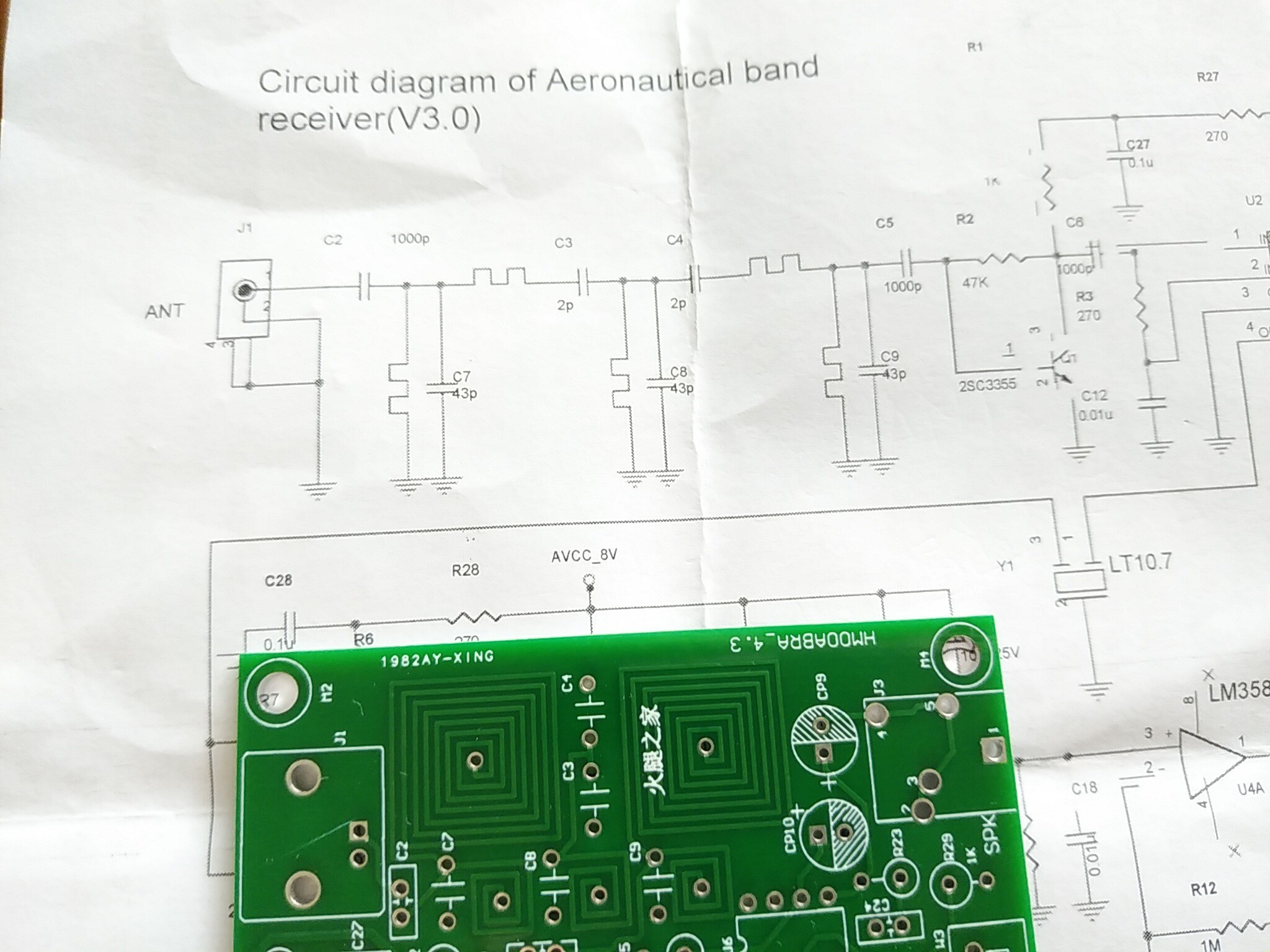
At first glance this seems reasonable. PCB inductors reduce assembly cost and simplify manufacturing. However, the receiver suffered from poor sensitivity, and the front-end filter became a prime suspect.
Using a nanoVNA, I measured the filter response and found significant passband irregularities.
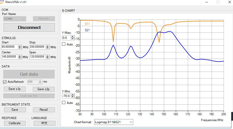
By
modifying component values, I was able to flatten the response and improve overall behavior.
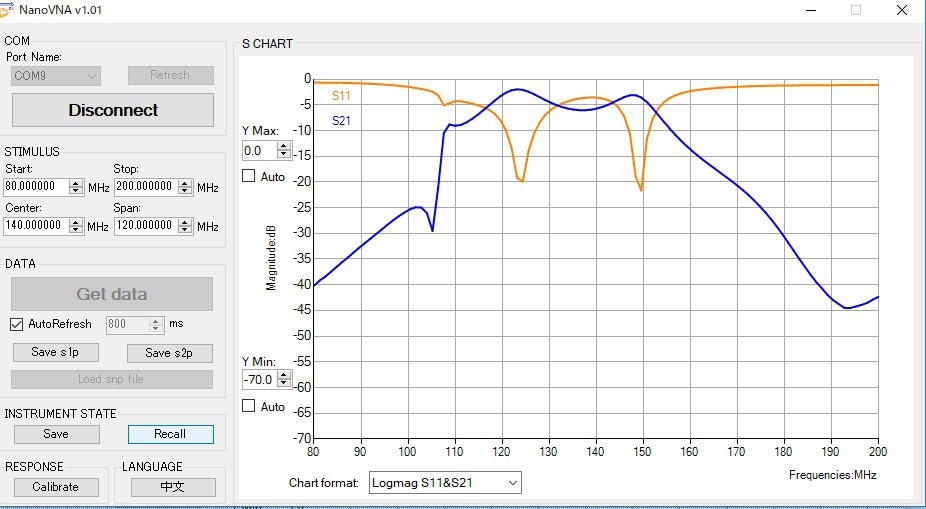
At this stage I believed the problem had been solved.
Then an Italian hobbyist asked a simple question:
"Why not use air-core coils?"
The answer was embarrassing: the original design had used them, and I had focused on improving the existing PCB filter rather than questioning whether the PCB inductors belonged there at all.
The passband shape had improved, but insertion loss remained much higher than desirable.
This raised a more interesting question: how much performance had been sacrificed when the original wound inductors were replaced by PCB spirals?
I still have an air-core version of the filter. Here is its measured response:
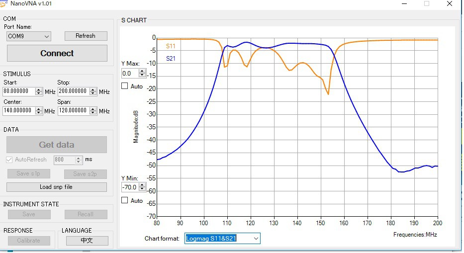
We should recognize that thePCB pattern coil is much different from the desired coil at VHF.
Sometimes the most useful engineering lesson comes from discovering that an wrong assumption was applied to the wrong starting point.
If you are interested in air band reception machine overall, please refer to the following project as well.
nobcha's Radio DIY Lab (Si4732,Si5351a, ESP32, RP2040 & RF Circuits)
 Cary W.
 Yang
Yang
 Abduulah Omran
 OhmByOhm