Close
0%
0%

Spresense Audio Jack as NTSC Video Output

Playing NTSC composite video on a TV using Sony Spresense's
192kHz 24bit HiRes Audio DAC — no code changes, just a WAV file.

Similar projects worth following
Playing WAV Files on a TV with Sony Spresense

What if you could turn a music player into a TV?

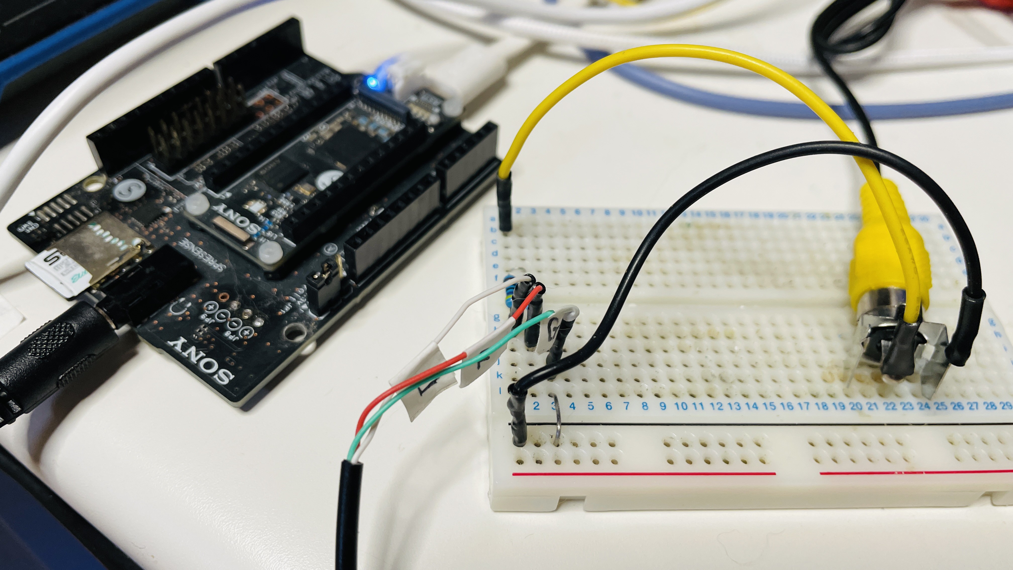
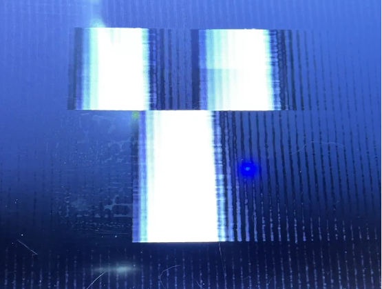
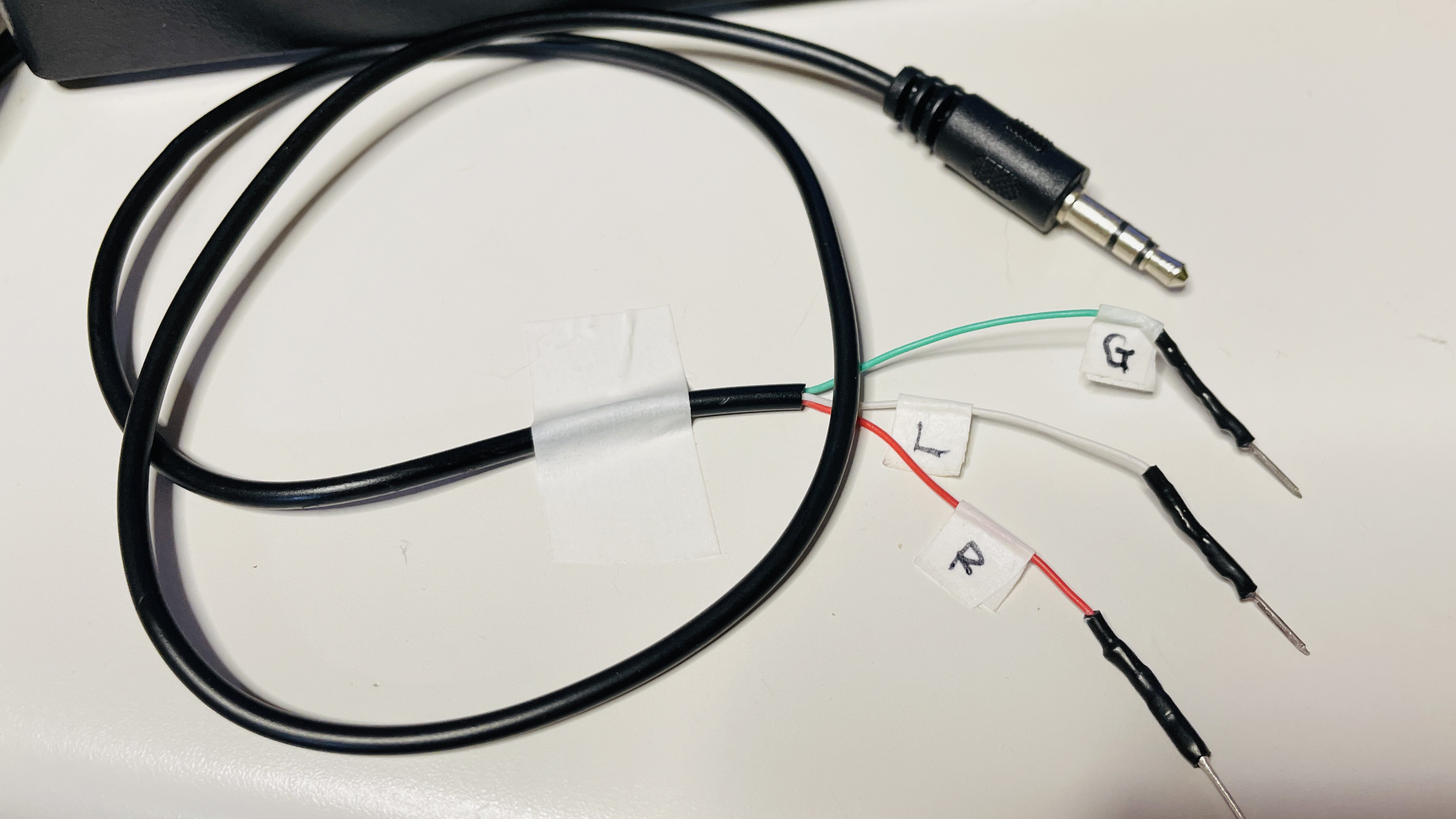
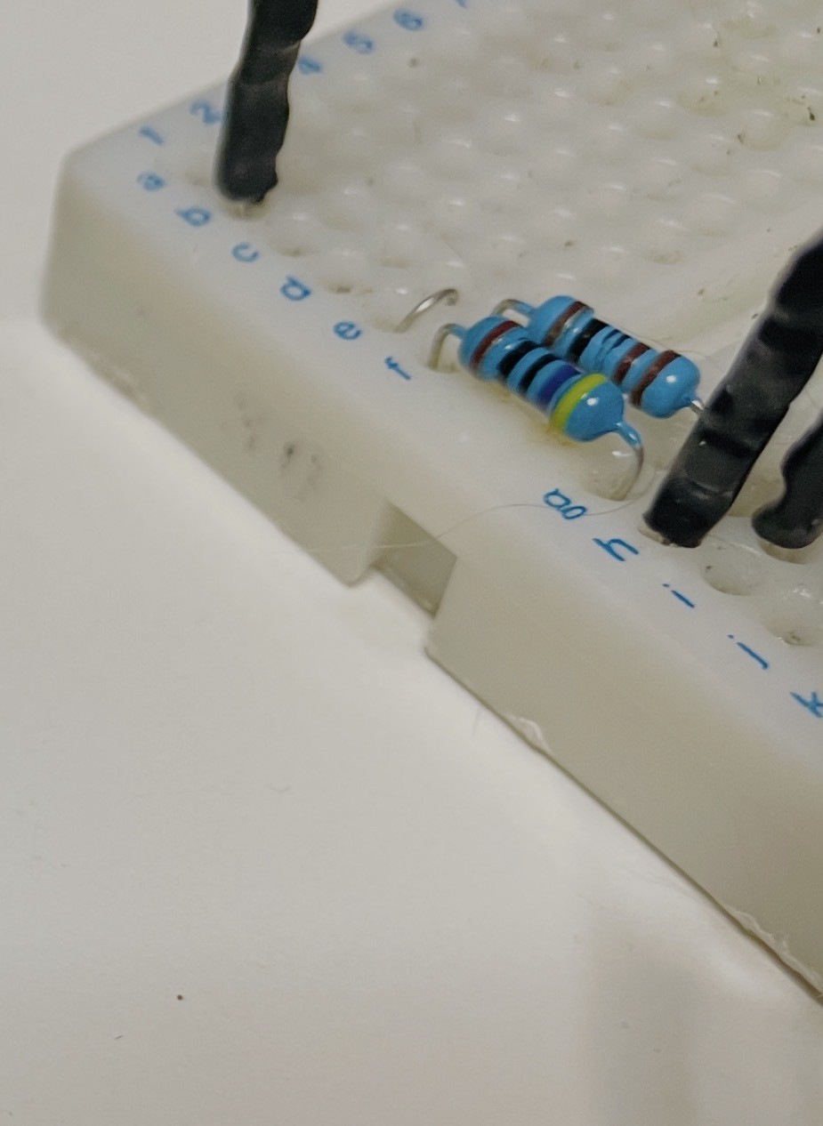
This project outputs NTSC composite video through the Sony Spresense's headphone jack — using nothing but two resistors. The Arduino code is Sony's official sample, completely unchanged. Only the file on the SD card is different.

The key insight: an audio signal and an NTSC video signal are both just voltage changes on a time axis. The only difference is the pattern.

Hardware:

  • Sony Spresense + Extension Board
  • 2 resistors (470Ω and 1kΩ)
  • RCA cable

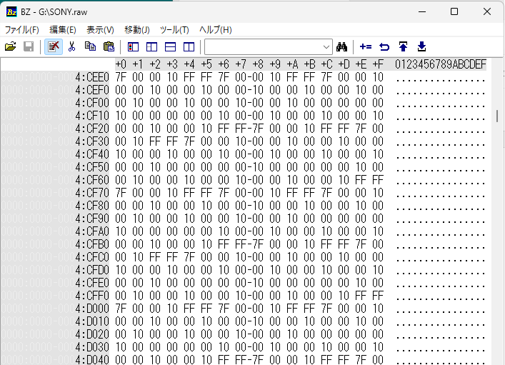
The NTSC waveform is pre-generated as a RAW file using Python, then played back at 192kHz 24bit Stereo. L channel carries video, R channel carries sync. Even Bad Apple!! runs on it.

  • Chapter 1: Introduction

    chrmlinux035 hours ago 0 comments

    One day, a question came to mind.

    "The signal coming out of the Audio Jack is just a voltage change. NTSC is also a voltage change. Aren't they the same thing?"

    What is an audio signal? It is what a microphone produces when it converts air vibrations into voltage changes. A speaker converts those voltage changes back into air vibrations. In other words, an audio signal is nothing more than "a voltage change on a time axis."

    So what is an NTSC composite video signal? It is a representation of sync signals and luminance signals — used by a TV to draw its picture — expressed as voltage changes on a time axis.

    Audio signal = voltage change on a time axis NTSC signal = voltage change on a time axis

    The essence is exactly the same.

    The only difference is the pattern of voltage changes.

    So if we output voltage that changes in the NTSC pattern from the Audio Jack, the TV should display an image.

    To do this: express the NTSC waveform as PCM data, save it as a RAW file on an SD card, and play it back with Spresense's Audio Player. The Arduino code is Sony's official sample player_hires.ino — unchanged. Only the filename needs to be different.

    -> player_hires.ino

    This concept recalls the movie Contact. In the film, video signals were hidden inside audio data. What we did here is the reverse — we intentionally designed video signals as audio data.

    The result?

    Video appeared on the TV. And not a single line of Arduino code was changed.

    This is not a story about "outputting video." This is a story about "turning a music player into a TV" — and the display content can be changed simply by swapping the RAW file. No recompiling. No re-flashing.

  • Chapter 2: Generation 1 - CPU Generates Video (CH32V003 Version)

    chrmlinux035 hours ago 0 comments

    Before the Spresense version, NTSC video output was implemented using a different approach — the CH32V003, an ultra-cheap 48MHz RISC-V microcontroller costing just a few cents each. Connect two resistors and it outputs NTSC composite video.

    -> x : ch32v003j4m6_NTSC

    The concept is simple:

    CPU (48MHz) → GPIO timing control → Resistor DAC (2 resistors generate voltage levels) → CVBS (Composite Video Signal) → TV

    The CPU generates video in real time — horizontal sync pulses, vertical sync pulses, and video data, all directly controlled by the CPU.

    This approach has many historical precedents:

    - AVR TVout library → ATmega + GPIO 
    - PIC TV output → PIC + GPIO
    - ESP32 Composite → ESP32 + I2S
    - Arduino TVout → Arduino + GPIO

    All follow the same pattern. The CPU generates video signal in real time. This is the defining characteristic of Generation 1.

    The CH32V003 version worked. However, this method has limitations.

    Because the CPU is generating video in real time, it cannot do anything else. To perform other tasks while outputting video, interrupts must be controlled with extreme precision. Any timing deviation causes video corruption.

    And more importantly — it never escapes the idea that "the CPU makes the video."

    This brings us back to the original question.

    "Audio signals and video signals are essentially the same thing. So the Audio DAC should be able to output video."

    Having built the CH32V003 version made this question even more meaningful. Outputting video via GPIO was already solved. What is the next stage?

    Not "CPU generates video" — but a world where "data becomes video."

  • Chapter 3: Generation 2 - WAV File Becomes TV (Spresense Version)

    chrmlinux035 hours ago 0 comments

    3.1 The Key Insight

    After completing the CH32V003 version, something became clear while working with the Spresense Audio library.

    Spresense has a feature called 192kHz 24bit HiRes Audio — sampling rate equivalent to professional audio equipment. It can update voltage 192,000 times per second.

    1 sample = 1/192000 sec = 5.2us

    The NTSC horizontal sync frequency is 15,734Hz. One line period is:

    1 line = 1/15734 sec = 63.5us

    Samples per line:

    63.5us / 5.2us = 12 samples

    12 samples can represent 1 line.

    Spresense has stereo output, so L and R channels can be controlled independently.

    L ch = VIDEO signal (luminance) R ch = SYNC signal (sync pulse)

    Mix them with 2 resistors and you get an NTSC signal.

    3.2 The Critical Realization

    Spresense has a sample called player_hires.ino. It simply plays a RAW file from the SD card at 192kHz 24bit Stereo. Nothing more.

    This code is not changed at all.

    Only the file on the SD card is changed. Put NTSC waveform data inside ntsc.raw, and the Audio Player outputs NTSC signal directly.

    The CPU is doing nothing in real time. It is simply playing back.

    This is the decisive difference from Generation 1.

    Generation 1 (CH32V003): CPU generates video signal in real time

    Generation 2 (Spresense): Python pre-generates the data, CPU only plays it back

    3.3 Circuit

    Just 2 resistors.

    Headphone Jack:

     
    L (tip) -> 470 ohm -> RCA center pin
    R (middle) -> 1k ohm -> RCA center pin
    G (sleeve) -----------> RCA GND


    3.4 PCM Values and NTSC Voltage Levels

    PCM_SYNC = 0x000000 # 0V = sync pulse 

    PCM_BLACK = 0x100000 # 0.3V = black level 

    PCM_WHITE = 0x7FFFFF # 1.0V = white level (maximum brightness)

    3.5 Result

    Oscilloscope measurements:

    Horizontal frequency : 15.97kHz (spec: 15.734kHz) Period : 62.56us (spec: 63.5us) Vpp : 960mV (spec: 1Vpp)

    Video appeared on the TV.

    But "video appeared" is not the accurate description. More precisely:

    "A WAV file was played on a TV."

  • Chapter 4: Technical Details - How to Generate ntsc.raw

    chrmlinux035 hours ago 0 comments

    4.1 Overview

    ntsc.raw is generated by a Python script. The flow is as follows:

    Python generates PCM data at 1 line = 12 samples, writes 262 lines per frame, saves to SD card as ntsc.raw. Spresense plays it back via AudioClass at 192kHz 24bit Stereo through the CXD5247 DAC. Audio Jack outputs L ch as VIDEO through 470 ohm and R ch as SYNC through 1k ohm. These are mixed by resistors and sent via RCA to the TV.

    4.2 Constants

    SAMPLE_RATE is 188811 Hz, fine-tuned from actual measurement. NTSC horizontal sync frequency is 15734.26 Hz. NTSC_H is 262 vertical lines. NTSC_W is 12 samples per line. SYNC_W is 2 samples for sync pulse width. BLANK_W is 3 samples for blanking width. VRAM_W is 9 samples equals 9 pixels. LINE_REPEAT is 3 lines per pixel row. VRAM_H is 87 lines.

    4.3 Writing One Sample

    24bit Stereo means 6 bytes per sample. L channel carries VIDEO data, R channel carries SYNC data, both written in 24bit little-endian format.

    4.4 Generating One Frame

    Lines 0 to 8 are the vertical sync period. 

    Lines 9 to 20 are the vertical blanking period. 

    Lines 21 to 261 are the active video period. 

    Within each active line, the first 2 samples are SYNC, 

    next 1 sample is BLANK, 

    and the remaining 9 samples carry VIDEO data mapped from VRAM.

    4.5 VRAM and Drawing

    VRAM is a 2D array of 9 columns by 87 rows. Each cell holds 0 or 1. draw_pixel writes to VRAM with bounds checking.

    4.6 font3x5 Character Drawing

    Each character is represented as a 15bit bitmap in a 3 wide by 5 tall dot matrix. draw_char iterates over each bit and calls draw_pixel accordingly.

    4.7 Loop Playback

    ntsc.raw contains only 1 frame. When Spresense reaches the end of the file it seeks back to the beginning and continues playing. This allows continuous NTSC video output from a file of only 1.8KB.

  • Chapter 5: Display Experiments - SPRESENSE Text and Bad Apple!!

    chrmlinux035 hours ago 0 comments

    5.1 HELLO WORLD Text Display

    The first display experiment was the word "HELLO WORLD", one character at a time, arranged vertically.

    With only 9 pixels of horizontal resolution, each character (3 pixels wide) had to be stacked vertically. Even so, the characters are clearly recognizable.

    5.2 SONY Text Display (switching every second)

    Next, the characters S, O, N, Y were displayed switching every second.

    This confirmed that dynamic content can be expressed as ntsc.raw.

    5.3 Bad Apple!! - Grayscale Video Playback

    The most ambitious experiment: the famous monochrome animation "Bad Apple!!" was converted to NTSC video and played back.

    A key advancement here is grayscale support — not just simple black and white.

    Each video frame is converted to grayscale, resized to 9x87 pixels, and brightness values are linearly mapped to PCM values.

    brightness 0 (black) -> PCM_BLACK (0x100000) 

    brightness 255 (white) -> PCM_WHITE (0x7FFFFF)

    The 24bit dynamic range enables smooth 256-level grayscale — impossible with 1-bit GPIO output.

    Resolution: 

    horizontal : 9 pixels 

    vertical : 87 lines (LINE_REPEAT=3, 180 active lines)

    Even at this extremely low resolution, Bad Apple!! is clearly recognizable. This is thanks to its high-contrast silhouette style, and the accurate luminance reproduction enabled by grayscale support.

    5.4 Comparison with Generation 1

    Generation 1 (CH32V003) vs Generation 2 (Spresense):

    Video generation : CPU real-time vs Python pre-generated Color depth : 1bit (black/white only) vs 24bit (grayscale) CPU load : High vs Zero Code changes : Required vs Not required How to update : Recompile and flash vs Swap SD card file Output : GPIO vs Audio Jack

    The most important difference: to change the video content in Generation 1, you must rewrite the code and flash the microcontroller. In Generation 2, just swap the file on the SD card. No recompiling. No re-flashing.

  • Chapter 6: Summary, Considerations, and Future Plans

    chrmlinux035 hours ago 0 comments

    6.1 What Was New Here

    This project can be summed up in one line:

    "Turning a music player into a TV."

    The technical novelty is not "outputting video." There are many historical examples of NTSC output via GPIO. What is new is where the signal comes from and how the video is created.

    Where: Audio Jack (headphone output) How: Simply playing back a WAV file

    The CPU does nothing in real time. It just plays back. All video content is pre-generated by Python and stored in ntsc.raw.

    6.2 Similarity to the Movie Contact

    In the movie Contact, an alien signal hidden inside audio data was decoded by Dr. Eleanor Arroway to reveal video. What we did here is the exact reverse.

    Contact : audio data -> analysis -> extract video This project : video data -> design -> play as audio file

    This project proves through implementation that audio and video are essentially the same thing.

    6.3 The Meaning of 192kHz 24bit

    Why Spresense? Because the CXD5247 DAC supports 192kHz 24bit HiRes Audio. This high sampling rate is the key to everything.

    192kHz means 1 sample = 5.2us. NTSC 1 line = 63.5us. That gives 12 samples per line.

    12 samples is a small number, but sufficient to express the basic structure of NTSC. And the 24bit dynamic range enables grayscale expression that was impossible with 1-bit GPIO output.

    6.4 Current Limitations

    Horizontal resolution : 9 pixels Vertical resolution : 87 lines (LINE_REPEAT=3) Color : grayscale only, no color Audio output : not possible simultaneously

    The fundamental reason for low horizontal resolution is that the analog output bandwidth of the CXD5247 DAC is approximately 96kHz (Nyquist limit), far short of the NTSC theoretical maximum bandwidth of 4.2MHz. But this is the current situation, not a permanent limitation.

    6.5 Future Plans - Expanding to 384kHz 32bit

    The next step is a USB-C external DAC supporting 384kHz 32bit UAC2.0, connected to a PC playing ntsc.raw directly.

    384kHz means 1 sample = 2.6us. NTSC 1 line = 63.5us. That gives approximately 24 samples per line.

    Horizontal resolution would roughly double from 9 pixels to around 20 pixels. And 32bit dynamic range would allow even more precise grayscale reproduction.

    6.6 The Spirit of the Maker

    During this development, an AI told me at the start that "NTSC via Audio DAC is impossible." Bandwidth insufficient, too few samples, physically impossible.

    But video appeared. Bad Apple!! played.

    "It is not that it cannot be done. We find a way."

    That is everything. Technical limitations certainly exist. But finding a way within those limitations is the engineer's job. Even at 9 pixels of resolution, Bad Apple!! is still Bad Apple!!

    6.7 Python Code

    # font3x5.py
    # 3x5 (ASCII 32 - 93)
    font3x5 = [
        0b000000000000000,  # 32 ' '
        0b010010010000010,  # 33 '!'
        0b000000000000000,  # 34 '"'
        0b101111101111101,  # 35 '#'
        0b000000000000000,  # 36 '$'
        0b000000000000000,  # 37 '%'
        0b000000000000000,  # 38 '&'
        0b000000000000000,  # 39 "'"
        0b000000000000000,  # 40 '('
        0b000000000000000,  # 41 ')'
        0b000000000000000,  # 42 '*'
        0b000010111010000,  # 43 '+'
        0b000000000010100,  # 44 ','
        0b000000111000000,  # 45 '-'
        0b000000000000010,  # 46 '.'
        0b001001010100100,  # 47 '/'
        0b111101101101111,  # 48 '0'
        0b010110010010111,  # 49 '1'
        0b111001111100111,  # 50 '2'
        0b111001111001111,  # 51 '3'
        0b101101111001001,  # 52 '4'
        0b111100111001111,  # 53 '5'
        0b111100111101111,  # 54 '6'
        0b111001001001001,  # 55 '7'
        0b111101111101111,  # 56 '8'
        0b111101111001111,  # 57 '9'
        0b000010000010000,  # 58 ':'
        0b000010000010100,  # 59 ';'
        0b000000000000000,  # 60 '<'
        0b000111000111000,  # 61 '='
        0b000000000000000,  # 62 '>'
        0b000000000000000,  # 63 '?'
        0b111101101101111,  # 64 '@'
        0b111101111101101,  # 65 'A'
        0b110101110101110,  # 66 'B'
        0b111100100100111,  # 67 'C'
        0b110101101101110,  # 68 'D'
        0b111100110100111,  # 69 'E'
        0b111100110100100,  # 70 'F'
        0b111100101101111,  # 71 'G'
        0b101101111101101,  # 72 'H'
        0b111010010010111,  # 73 'I'
        0b001001001101111,  # 74 'J'
     0b101101110101101,...
    Read more »

View all 6 project logs

Enjoy this project?

Share

Discussions

Does this project spark your interest?

Become a member to follow this project and never miss any updates