 Parallel Logic
First action when receiving new boards is to photograph them:
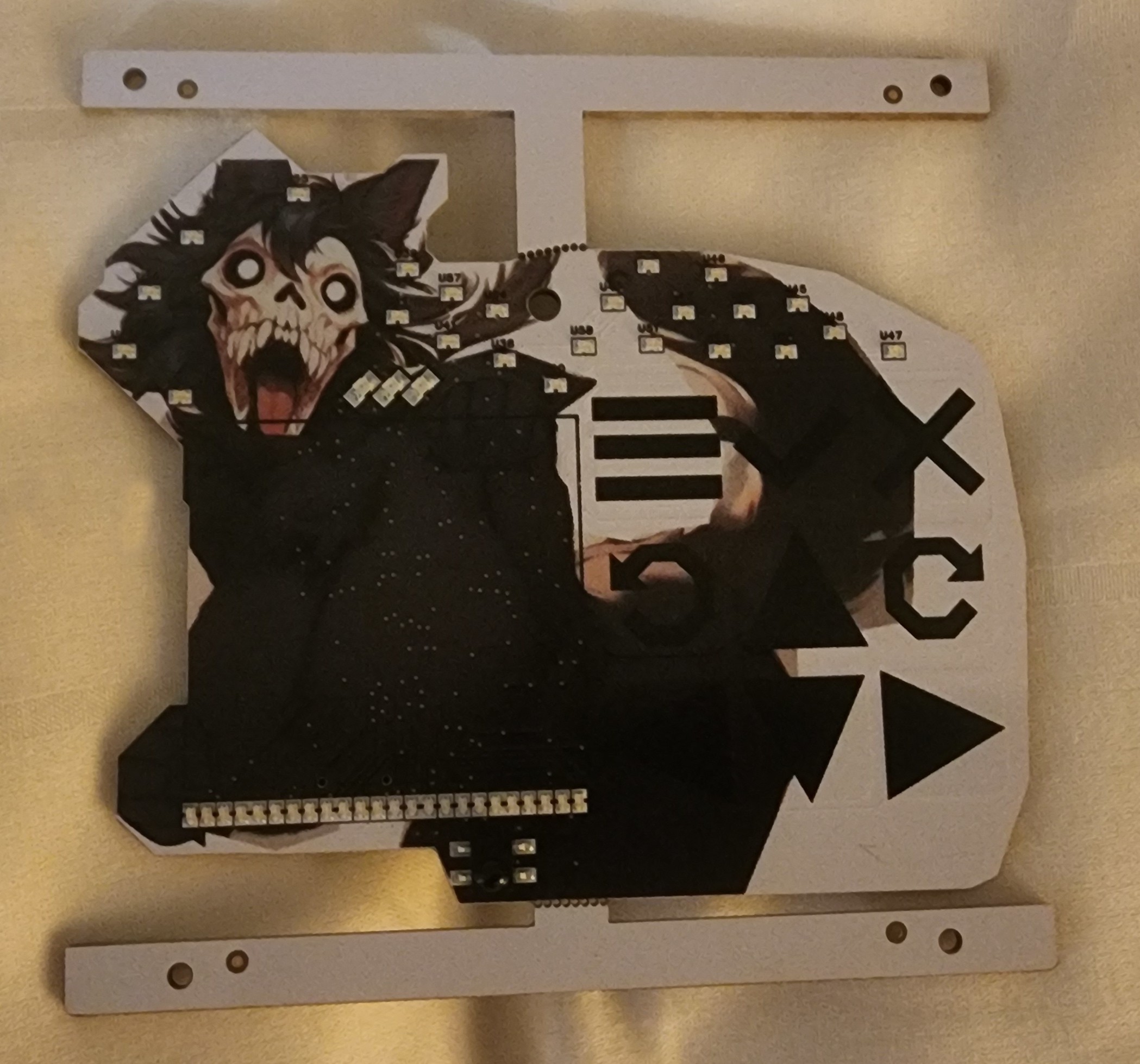
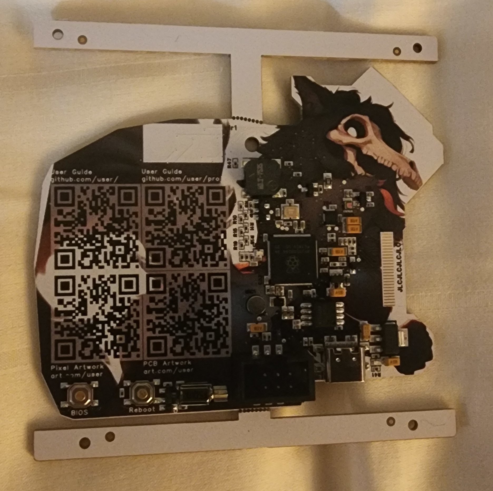
One detail that irks me is the small white pull-back around every pad. That's a property of the color silkscreen technology, but it's not something you see in the CAD render and does hide/obscure the artwork a little.
I didn't take any effort to remove the black silkscreen, so you can see the reference designators around the entire back side, particularly over the white background
A small note: the fab house has a minimum order of 5 PCBs, but I chose to only have 4 populated with parts - that gives me a clean copy of just the PCB itself that I can check continuity on the traces (workmanship) independent of the parts themselves (ex, a chip may internally close the connection between two VCC pads, where the PCB may have otherwise treated them independently).
First power-ON is the most nerve-racking part of the process in my experience: either the board works fully or it doesn't - it's a very binary fork in the road. It's normally worth taking this step very slowly - I have spare populated prototypes, yes, but those are really for backup/experiments during development).
- Did a resistance check between power (3v3) and ground. Got 600 ohms. Not terribly insightful aside from there at least shouldn't be a dead short between power and ground, so that's good enough to proceed.
- Observed that there is a mechanical interference between the screen and the edge of the PCB (her hand holding the screen). I had specifically planned around this, but still ended up with interference - turns out misread the screen mechanical drawing and though the cable was much longer than it ended up being, so definitely a fix for the next prototype... I later used a dremmel to shave off that part of the PCB so I could assemble the screen properly.
- I applied 3.3V with a 100 mA OCP limit on my power supply, with the thought that if this design was defective, it should hopefully not draw so much power that it destroys itself- trying to preserve the prototypes as long as I can
- The 3.3V power indicator LED came ON (much brighter than I expected, will be decreasing the 1~5mA current draw notably on that LED in the next prototype). Power draw is around 100 mA, where is all that power going...
- Poking my finger around on the PCB to try to find the hot spot, I misdiagnosed the problem as coming from the crystal, and I went down a rabbit hole trying to debug that. In the coming weeks, I would determine it was the neighboring IMU where I swapped the interrupt and VCC pins, putting it in a half-driven configuration that loosely shorted power to ground and drawing excessive power. There is an option to de-solder one part and observe the impact on the power draw that way to definitely prove where the issue is coming from, but I didn't pursue that path here, in part because this is a 2-sided PCB design and makes it hard to rest the board on a hot plate and not inadvertently remove part from both side of the PCB.
- But pushing forward, can it be programmed despite the high power draw? Plugging in via USB in BOOTSEL mode and it successfully manifests as a USB drive just like the pico2 (I was using this for software development up to this point), so far so good. Uploaded a simple blink sketch (driving the debug LEDs), and nothing...
- However, adding in Serial printout works normally, so the chip is running the bit file, but not driving the LEDs... issue was the pico2 is a RP2350A chip, and in order to program the larger (more pins) chip, you need one that enables the extra GPIOs. When I set the Arduino IDE to MyMakers RP2350B, that enabled the extra pins, including the LEDs on the upper bank, and the debug LED blinked.
The objective now is to test each sensor/peripheral to a bare minimum degree necessary to make a go/no-go determination to move forward. Simplest one after the debug LEDs is the motor since it's literally the same code, just running on a different GPIO pin. Here's a "blink" program that ran on the motor for 1 second ON, and 1 second OFF (sounds just like an old school flip phone imho):
Questions/comments/thoughts/requests encouraged
Discussions
Become a Hackaday.io Member
Create an account to leave a comment. Already have an account? Log In.