• Archer-2: Development and Flight Testing

    kruthick jothimani1 天前 0 comments

    Rocket design

    Archer-2 is an exact copy of Archer-1; only the electronics were changed.

    Apogee Detection

    This time, I removed the tilt sensor and used a pressure sensor to measure atmospheric pressure. As the rocket’s altitude changes, the atmospheric pressure also changes. By tracking these pressure changes, I could estimate the altitude and detect apogee.

    Code Logic

    #include <Wire.h>
    #include <Adafruit_BMP085.h>
    #include <Servo.h>
    
    Adafruit_BMP085 bmp;
    Servo parachuteServo;
    
    float groundPressure;
    float currentAltitude;
    float maxAltitude = 0;
    
    bool launched = false;
    bool deployed = false;
    
    void setup() {
      Serial.begin(9600);
    
      parachuteServo.attach(9);
      parachuteServo.write(0);   // Servo closed position
    
      if (!bmp.begin()) {
        Serial.println("BMP180 not found!");
        while (1);
      }
    
      delay(1000);
    
      // Take ground pressure when Arduino turns on
      groundPressure = bmp.readPressure();
    
      Serial.println("System Ready");
    }
    
    void loop() {
      // Read current pressure
      float pressure = bmp.readPressure();
    
      // Calculate altitude relative to ground
      currentAltitude = 44330.0 * (1.0 - pow(pressure / groundPressure, 0.1903));
    
      // Store highest altitude reached
      if (currentAltitude > maxAltitude) {
        maxAltitude = currentAltitude;
      }
    
      // Rocket has launched after reaching 1 m
      if (maxAltitude > 1.0) {
        launched = true;
      }
    
      // Detect apogee:
      // Current altitude is 1 m lower than maximum altitude
      if (launched && !deployed && currentAltitude <= (maxAltitude - 1.0)) {
        parachuteServo.write(180);   // Deploy parachute
        deployed = true;
    
        Serial.println("APOGEE DETECTED - PARACHUTE DEPLOYED");
      }
    
      Serial.print("Current Altitude: ");
      Serial.print(currentAltitude);
    
      Serial.print("  Max Altitude: ");
      Serial.println(maxAltitude);
    
      delay(100);
    }

    The code uses two variables: Max Altitude, which stores the highest altitude reached, and Current Altitude, which stores the rocket’s present altitude. When the current altitude becomes lower than the maximum altitude, the rocket has passed apogee and started descending.

    Test Flight

    This method worked perfectly. The parachute deployed successfully, and the rocket landed safely. Finally, after many attempts and failures, the recovery system was complete.

  • Archer-1: Development and Flight Testing

    kruthick jothimani1 天前 0 comments

    Rocket design

    Archer crashed badly and broke into many pieces, so I built a new version with larger fins and a more durable nose cone. Other than these changes, the design remained the same as Archer-0.

    Fins

    The fins were printed as a single piece. Printing and attaching them separately could cause alignment errors, which might make the rocket tilt to one side during flight.

    Flight Test-1

    I would consider this test the most successful one. The parachute deployed perfectly, and the rocket landed smoothly.

    However, it also tested my patience. This was the fifth flight test. The previous four tests had failed for different reasons, including misfires, launch-rail jams, and using a motor that was too small to lift the rocket properly.

    In one test, the rocket only reached about 2–3 meters before falling back down, which broke the fins. I repaired the damage by gluing the fins back in place.

    After several failed attempts and repairs, the rocket finally completed a successful flight and recovery.

    Flight Test-2

    I launched the rocket again on another day, but this time the parachute did not deploy. I still do not know the exact reason for the failure.

    I suspect that the problem may have been with the tilt sensor. It used a small ball to complete the circuit when tilted. If the ball became stuck or the rocket did not tilt far enough, the circuit may not have been completed and the deployment system would not activate.

    Next step 

    I need to find a more robust method of detecting apogee. Using tilt is not reliable, especially for Electron, because the rocket may remain upright while descending.

    For a propulsive landing, the landing motor must ignite while the rocket is upright, so the vehicle may not tilt enough to trigger a tilt-based deployment system.

  • Archer-0 Development and Flight Testing

    kruthick jothimani1 天前 0 comments

    Parashoot deploment system

    This time, I switched to a more robust system. Instead of the homemade PVC-pipe and copper-piece tilt switch, I used an off-the-shelf tilt sensor.

    I also replaced heated wire, and match-based release methods with a servo-operated parachute deployment mechanism. The earlier methods could work once but fail during another test, so I wanted a more repeatable solution.

    An Arduino Uno was used to read the tilt sensor and control the servo. When the required tilt condition was detected, the servo released the parachute.


    Flight Test 1

    Due to a weak parachute cord, the parachute deployed but was not securely attached to the rocket. As a result, the rocket fell to the ground while the parachute flew away.

    Flight Test 2
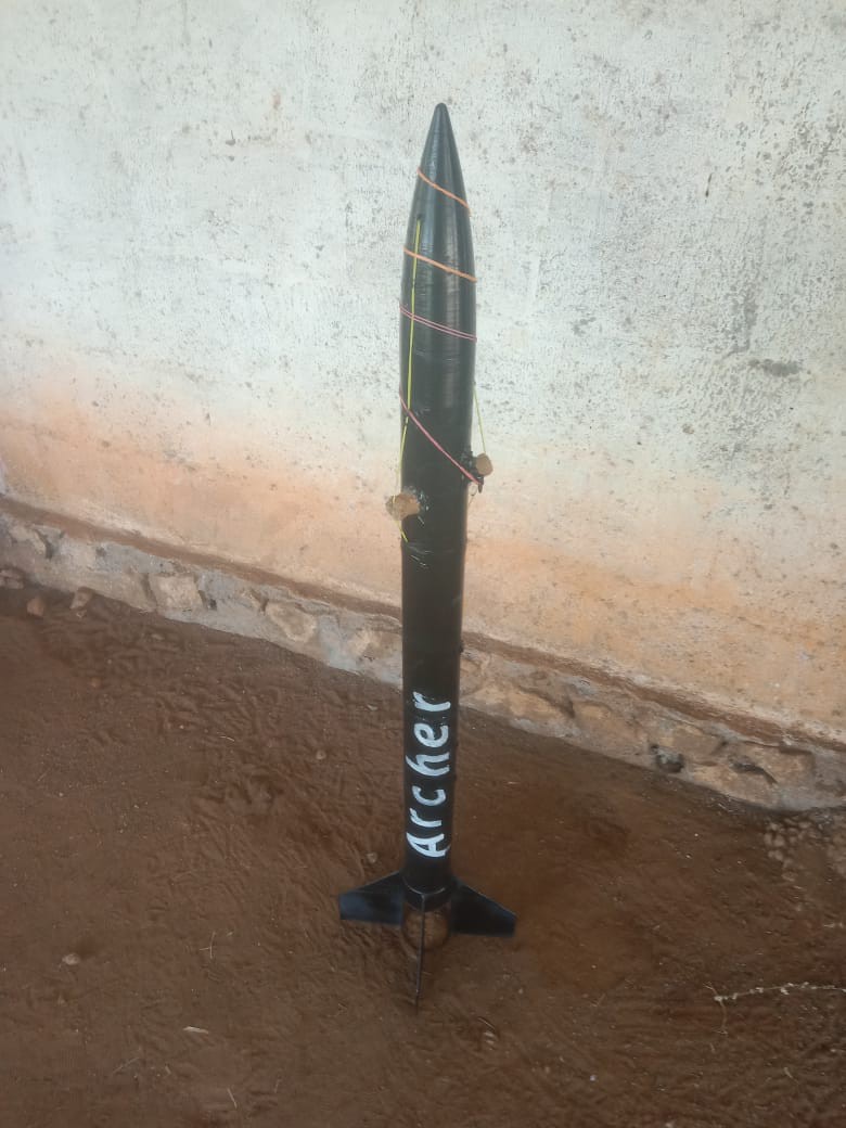
    The next morning, I launched the rocket again. During the flight, the parachute deployed successfully, and the rocket landed in a tree. However, the nose cone broke during deployment.
    Flight Test 3

    I repaired it using glue and launched it again the same day. Unfortunately, the glue jammed the deployment system during the second flight, causing the rocket to crash.

  • ANA: Development and Flight Testing

    kruthick jothimani1 天前 0 comments

    Parachute Deployment System

    ANA used the same general parachute-deployment idea as Raven: a rubber band held the parachute in place until the release mechanism was activated.

    However, instead of using only a heated wire to cut the rubber band, I attached a match head near the rubber band and connected it to the electrical circuit. When the deployment circuit was triggered, the match ignited and burned through the rubber band, allowing the nose cone to open and the parachute to deploy.

    This design was intended to provide a more reliable release than the previous wire-only mechanism.

    Testing

    Result

    Due to the strong wind during the rocket’s descent, the match did not burn through the rubber band. As a result, the parachute did not deploy, and I was unable to recover the rocket.

  • Raven: Development and Testing

    kruthick jothimani1 天前 0 comments

    Goal

    After Dragon failed, I gained valuable knowledge from the Yellow Brothers tests and achieved success with Spider. Based on what I learned, I decided to build a rocket with a recovery system.

    Rocket design

    I used the same basic design as Dragon: two body tubes joined with 3D-printed couplers, along with a 3D-printed nose cone and fins. It also used the same motor configuration as Spider.

    Parashoot deploment system

    This time, I removed the sensors and microcontroller because I did not think a flame-based system would be reliable. KNSU motors mainly produce smoke, and most of the combustion happens inside the motor, so there may not be enough visible flame for a sensor to detect consistently.

    Instead, I used tilt as the parachute-deployment trigger. I made a simple tilt switch using a PVC pipe containing conductive material, such as copper pieces. Two screws were placed at one end of the pipe. When the rocket reached apogee and began descending, the pipe tilted, allowing the conductive material to connect the two screws and complete the circuit.

    The circuit powered a heating wire wrapped around a rubber band. When the wire heated up, it cut the rubber band and released the parachute.

    Testing

    Result 

    Because the parachute was not secured properly, it deployed during mid-flight. The rocket then drifted a long distance sideways before crashing into a coconut tree.

  • Spider: Development and Testing

    kruthick jothimani1 天前 0 comments

    Goal

    Spider was developed to test the new motor I made. At the same time, I was learning about rocket stability and how to design a stable rocket. Spider provided a useful platform to test what I had learned.

    Reference Video: Homemade Motor Development

    While searching YouTube for KNSU motor videos, I came across this video. It was very useful in helping me develop my own motor.

    All credit for the original video goes to its creator. This project is independent and is not affiliated with or endorsed by the channel.

    Motor

    This motor used a 1-inch CPVC pipe with two end caps. Metal washers were used as the nozzle, which was held in place with M-Seal.

    Unlike the previous motor, I used a melted KNO₃-and-sugar mixture and cast it into the pipe. This produced a denser and more uniform grain than the earlier manually compacted method.

    Rocket Design

    Spider was designed to be stable by using a slim body tube and placing the center of gravity (CG) ahead of the center of pressure (CP). I mounted the fins near the bottom of the rocket and added weight inside the nose cone to move the CG forward.

    This configuration made the rocket more resistant to unwanted rotation during flight. I also performed a string swing test to verify its stability.

    Testing

    Test Result

    Unexpectedly, the rocket flew much higher than I expected. It was a huge success, and I never thought a homemade motor would perform this well.

    Conclusion

    Melting and casting the fuel worked well, producing a denser and more uniform grain. However, it also made ignition more difficult. The Spider motor required several ignition attempts before it started successfully. Apart from the ignition issue, the test proceeded as expected.

  • Yellow brothers: Development and Testing

    kruthick jothimani2 天前 0 comments

    Goal

    Yellow Brothers was developed as a simpler test platform after the earlier rocket tests failed. The goal was to test a basic rocket configuration with fewer systems, understand real-flight behavior, and improve the design step by step before adding more complex recovery or electronics systems.

    Development

    The rocket was built using a simple cardboard body tube, basic fins, a nose cone, a motor mount and it uses dry fuel motor. The design was intentionally kept lightweight and simple so that I could focus on the motor performance, launch stability, and structural reliability.

    Large Rocket Test

    Result

    Due to overpressure caused by the small nozzle throat diameter, the motor burst.

    Small Rocket Test

    Result

    A Successful Failure

    This was the first rocket to leave the launch rail and fly. However, because the center of pressure was ahead of the center of gravity, the rocket was unstable. After a few seconds, it crashed into the ground.

    I still consider this a success because the rocket successfully lifted off and flew for several seconds.

    Conclusion

    These simple test failures showed me that I still have a great deal to learn before reaching my final goal of propulsively landing a rocket.

    The motor worked in some tests but failed in others. The nozzle performance was inconsistent, and the manufacturing process was not safe or repeatable. Even with heavy compaction, the propellant grain was not uniform enough.

    Next Step

    For the next stage, I need to develop a safer and more reliable motor system—one that performs consistently and produces a repeatable thrust curve in every test.

  • Dragon: Development and Testing

    kruthick jothimani2 天前 0 comments

    Why Dragon Was Developed

    Dragon was developed as my first experimental rocket to test homemade motors in a real flight environment.

    Static motor tests can show whether a motor ignites and produces thrust, but they cannot show how the motor, rocket structure, stability, and recovery system behave during an actual launch. Dragon was built to gain practical experience in rocket design, flight testing, parachute recovery, and deployment-system reliability.

    The goal was not to create a perfect rocket on the first attempt, but to learn from each test and use the results to improve future versions.

    Dragon Airframe Design and Construction

    Dragon’s body consists of two 65 mm diameter cardboard shuttle tubes joined with 3D-printed couplers. The nose cone is also 3D printed.

    Parachute Development

    To keep the design inexpensive and lightweight, I used plastic garbage bags as the parachute material and nylon thread as the suspension lines to maintain its shape.

     Parachute Testing

    To check the parachute’s reliability, I attached a weight equivalent to the rocket’s mass and tested it several times. The parachute deployed properly, slowed the descent effectively, and landed safely. Even after multiple tests, the low-cost plastic material held up well.

    Parachute Deployment System

    I chose an unusual method for the parachute deployment system. I used four flame-sensor modules placed around the motor, facing the exhaust, to detect ignition. The system also included a pyrotechnic deployment charge with an electric igniter, controlled by a relay and an Arduino.

    At that time, I was unaware of the risks of using a relay in a rocket. Strong vibration or shock during flight could potentially trigger the relay unintentionally.

    The code logic was simple: when any flame sensor detected the motor exhaust, the system recognized that ignition had occurred. When none of the sensors detected flame anymore, the system identified motor burnout and triggered the deployment charge to release the parachute.

    Parachute Deployment System Testing

    Dragon Flight Test 1

    The rail guides were not secured properly to the rocket. During liftoff, the rocket became stuck on the launch rail, and the motor broke the motor mount and came out of the rocket.

    Dragon Flight Test 2

    The motor seal was not secure, causing the motor to behave like a flowerpot-style firework instead of producing controlled thrust.

    Conclusion and Next Steps

    Both tests failed, but they showed that I needed to take a more step-by-step approach. Instead of trying to test every system at once, I decided to begin with only the motor and a simple cardboard-tube rocket. After achieving a reliable basic flight, I could then add and test the parachute recovery system separately.

  • Testing Different Solid Rocket Motors and Measuring Thrust

    kruthick jothimani4 天前 0 comments

    Goal

    The goal of this test is to try different casing materials and, unlike the previous test, measure how much thrust the motor produces.

    Fuel casting

    The same method as before was used to cast the fuel. A 65/35 fuel mixture was used, and the fuel and oxidizer were finely ground before being tightly packed into the casing.

    Test Setup

    A weight scale was used to measure the thrust, and the readings were recorded using a phone camera. A load cell could also have been used to log the thrust more accurately, but since only an approximate thrust value was needed for this test, I chose this simpler approach.

    Results

    Materials such as uPVC could not withstand the heat and deformed after the test. CPVC performed much better, making it more suitable for this application.

    The thrust measurements showed that the motor generated approximately 30 N of peak thrust, with a burn time of about 3 seconds.

    Next Step

    The next step is to test the motors on the actual rocket. A motor may perform well on a test stand, but a real flight will show how it behaves under realistic conditions. This will also help me gain more practical knowledge and experience in rocketry.

  • First Attempt at Building a Solid Rocket Motor

    kruthick jothimani06/19/2026 at 05:05 0 comments

    Goal

    To see weather a homemade solidmotor can ingnight and burn

    What I Built

    • Motor casing: 18 mm ID CPVC tube
    • Propellant: KNO₃ + sugar
    • Nozzle throat: 4 mm

    Motor                                                                                                                                                   


    To keep the design simple, I chose a basic grain geometry: a solid cylinder with a central bore hole. The nozzle was simply a washer with a 4 mm hole.

    Fuel Casting

                                                                                                                  The fuel mixture contained 65% KNO₃ (oxidizer) and 35% sugar (fuel). Both components were separately ground into fine powders, blended, and compacted into the casing to increase the packing density. Finally, the central bore hole was slowly made by hand using a drill bit.

    Test Setup

    Result

    The motor ignited successfully and produced flame with lot of sound.
    The thrust is not messured, but this test confirmed that the casing, igniter, and nozzle design worked.

    Problems Found

    • Thrust changed during the burn.
    • Propellant grain was not perfectly uniform.

    What I Will Change Next

    For the next version, I will improve grain consistency and test a different nozzle throat diameter.

    This was the first major step in the Electron project. Before developing the full TVC rocket, I needed to understand how a small solid rocket motor behaves, how reliable the ignition is, and how much thrust can be produced from a simple test motor.

    The goal of this first attempt was not to make a perfect motor, but to learn the basics of motor testing, ignition, burn behavior, mounting, and safety. This test helped me understand that solid motors are powerful but difficult to control because, once ignited, the thrust cannot be throttled or stopped like a liquid or hybrid engine.

    Next step

    The next step is to measure the motor thrust and test different fuel-mix ratios, grain widths, and nozzle throat diameters to see how they affect performance. Then, we can draw a conclusion.