 PieterV
How did I get here?
One of the many projects on my to do list was “building an analog joystick from scratch”.
It had been there for several years, and recently I finally accepted the challenge.
Considerations
My wish list was not very long.
I wanted to build a joystck out of a few standard parts and some that I could comfortably 3d print on my Ender 3. It had to be compact so it would fit in my desk (which has a thickness of 18mm) without protruding from the bottom.
Using potentiometers did not appeal to me, because I wanted the final product to be compact and mechanically simple. Therefore I chose a cheap Hall-sensor.
It had to be easy to assemble for anybody with basic skills, feel reliable and it should of course look good (very subjective, I know).
After building it, basic functionality would need to be tested. Since I have some experience with Arduino, I chose this platform as the intermediary between the joystick and my PC.
I used Processing for producing the necessary visualisation PC software.
The mechanism
So, how does a joystick translate your hand’s movements into an electrical signal?
Traditionally, joysticks use a mechanical transmission that translates the lateral motion of the joystick into two rotational movements that are driving two potentiometers, hence creating the electrical signals we need.
Systems like this tend to be rather bulky and contain many parts. I wanted something simple and compact.
After searching the internet for possible solutions, I finally came across a mechanism that looked very promising. I drew the components I needed in my favourite CAD program and started 3Dprinting. It took quite a couple of iterations to arrive at a functional setup that was easy to assemble.
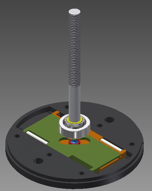
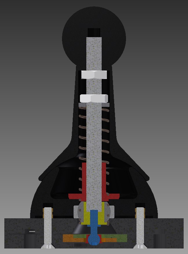
The final height of the mechanism was just 3mm, so this would definitely fit in my desk.
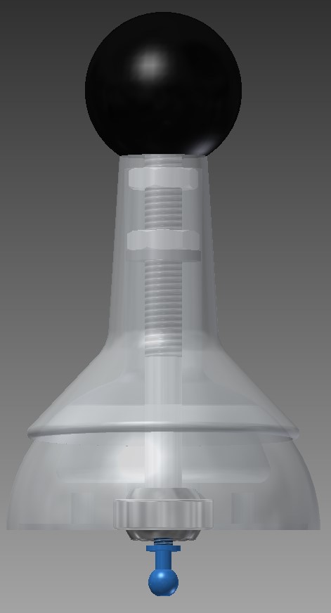
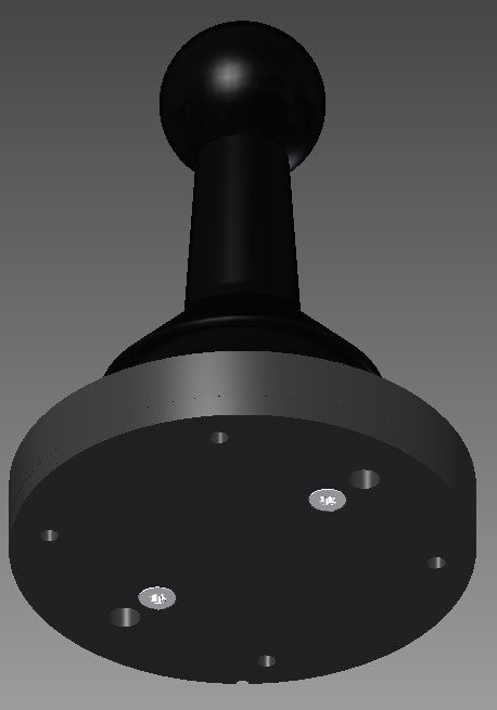
Total height of this joystick is 98mm, and the mechanism has a diameter of 70mm.
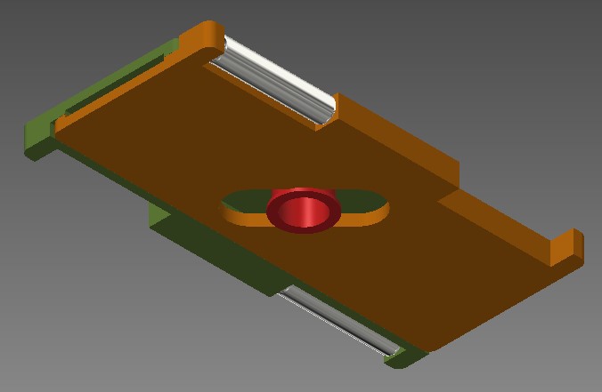
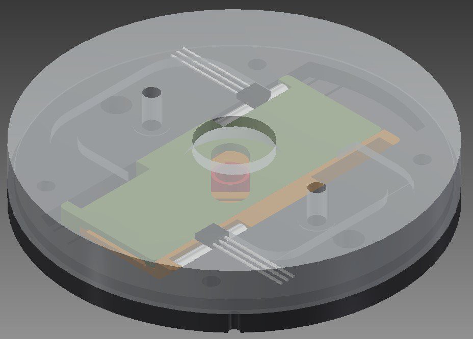
Movements of the stick travel through a spherical bearing. The low end of the stick has a ball shape, that moves either of two horizontal plates, depending on the direction of the movement. Attached to both plates are two cylindrical Neodymium magnets, that slide in front of the Hall-sensors. Thus, any movement of the stick will be translated into two seperate electrical signals (up-down and left-right).
The design of the plates ensures minimal friction. Besides, the same design is used twice: all you need to do is flip one of them to make a complete set.
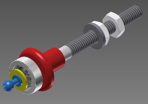
The shaft is fixed in place by the sperical bearing at the low end. The ball-shaped blue part will fit inside the red part that slides in the center of both plates. Any movement of the shaft will result in a respective movement of the small ball.
I cut a partial thread on the shaft to be able to fit two nuts: one to adjust the tension of the spring that will center the shaft, and one to define the height of the part that covers the shaft assembly. That part is ultimately clamped between the nut and the ball that screws on top of the shaft, and swivels across the dome.
Between the red part that slides over the shaft, and the washer that is seated against the bottom nut, I mounted a compression spring. This results in a reliable return-to-center mechanism. The non-threaded end of the shaft is glued into the yellow axle part that fits inside the bearing. The ball head screw is screwed into the other end of the yellow axle part.
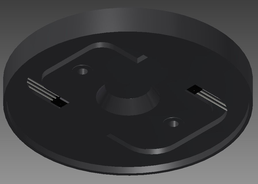
The Hall-sensors are mounted in the top part of the mechanism. I simply glued them in place.
The wires (3 for each sensor: 2 for power supply and 1 for signal) are guided through the part and exit the bottom part via two small holes in the adjacent carrier part.
If you seal the sensors and wires with silicone compound, you would essentially end up with a waterproof joystick.
After placing the top part, the shaft, the spring and the shaft cover, final assembly is done by two M3x16 screws from the bottom. These two screws keep the entire assembly together.
Both Hall-sensors were hooked up to two analog inputs of an Arduino Nano. A simple program reads both analog values, maps them to a desired range and outputs them through the serial port to my PC.
On my PC, a Processing program shows both values as a crosshair position.

Discussions
Become a Hackaday.io Member
Create an account to leave a comment. Already have an account? Log In.