 Jeroen V
DDS would give me a stable sine instantly, but let's do it the hard way. Low-THD analog sine oscillator usually means Wien bridge, for a stable frequency you need a quartz crystal, we need both.
All the files can be found here: CodebergQuarzWien
Let's take a look at the schematic:
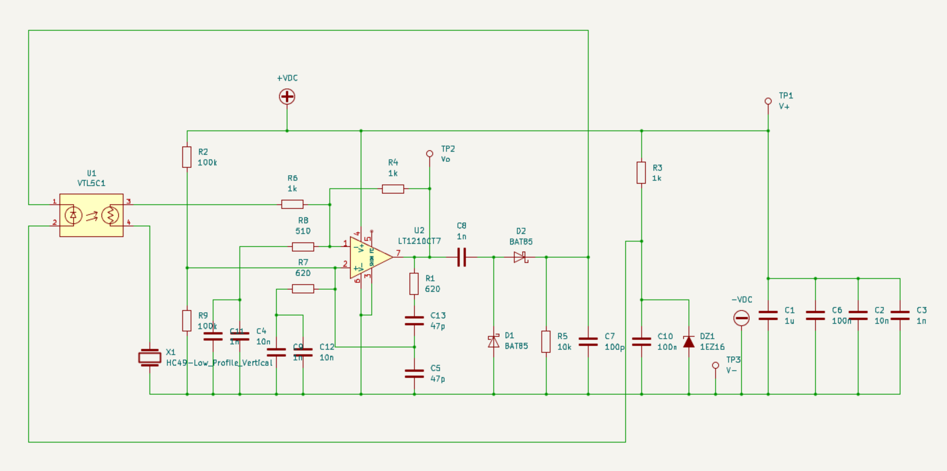
First note that we have only one active component, the LT1210, a 35MHz current feedback amp, operating on 30V. R2/R9 give it a bias of 15V.
For a Wien bridge we need an amplification of 3, the LT1210 is operating as a simple non-inverting amplifier, R4/R8 (AC grounded through C4 and C11) give it an amplification of "almost 3".
R1/C13 and R7/C5 are the standard Wien feedback circuit (with C9/C12 blocking DC through R7). If you calculate the frequency based on 47p and 620 ohm you will see that it seems too high, this is because the LT1210 has a phase shift of about 12 degrees at 4MHz, so the actual frequency is around 4MHz.
So far nothing special. The interesting part is the amplitude control system. U1 is a "vactrol". Basically just a LED and an LDR. The first time I tried this circuit I actually used a simple red led with an LDR, it was inspired on the old electronic organ volume pedals.
All it does is changing the resistance value by shining light on a cadmium sulfide cell. The VTL5C1 is also used in analog guitar effects.
This is how the control system works: The AC output of the LT1210 is rectified by D1/D2 and a 16V voltage is created by R3/C10/DZ1, a simple zener circuit. Since the default amplification is less than 3 the oscillator is initially not running and the rectified voltage is zero. Which puts the LED of the vactrol and R5 in series over the 16V zener voltage, about 1.4mA will flow through the led and the CdS cell starts to conduct.
This lowers the effective AC resistance in the lower feedback leg enough to raise the amplification to more than 3, the minimum LDR resistance at 1.4mA is about 1k, add R6 and there is about 2k parallel to R8, giving a maximum amplification of about 3.5x and the oscillation starts, raising the voltage at the output of the rectifier, lowering the voltage difference over the LED, until it's about 1.6V and the amplification is at the steady state point.
By now you have probably figured out that the "little bit extra amplification needed for oscillation" needs an AC current not only through the LDR, but also through X1, so it can only oscillate on the frequency for which X1 has a low impedance (series mode resonance), giving the oscillator a quartz stable frequency. X1 also limits the bandwidth of the signal through the LDR thereby reducing LDR noise. A quartz crystal can handle a limited amount of power, usually around 1mW. R6 and the LDR limit the power dissipation of X1 during startup and in the steady state. When the amplification is a little bit higher than 3 the LDR has about 23k resistance, with 20Vpp output this gives 2.35V rms over R5+LDR+X1. At an internal series resistance of 130 ohm for X1 the power dissipation of the crystal is about 1.2uW. Very low, and that is good news, high power dissipation in a quartz crystal would generate distortion.
One other noteworthy thing: the value of C7, the rectifier needs a bit of capacitance to build up some DC, but the value seems quite low for a Wien bridge, the time constant R5/C7 is only 1us and any current through the LED will lower that. The reason: the CdS cell has a time constant of its own, about 30ms, LDRs are slow, if we would add another filter in the control loop with a comparable time constant the filter would become second-order, creating a slow oscillation in the amplitude. The normal first-order low pass needed in the control loop is already there, it's the LDR itself.
Let's take a look at the spectrum:
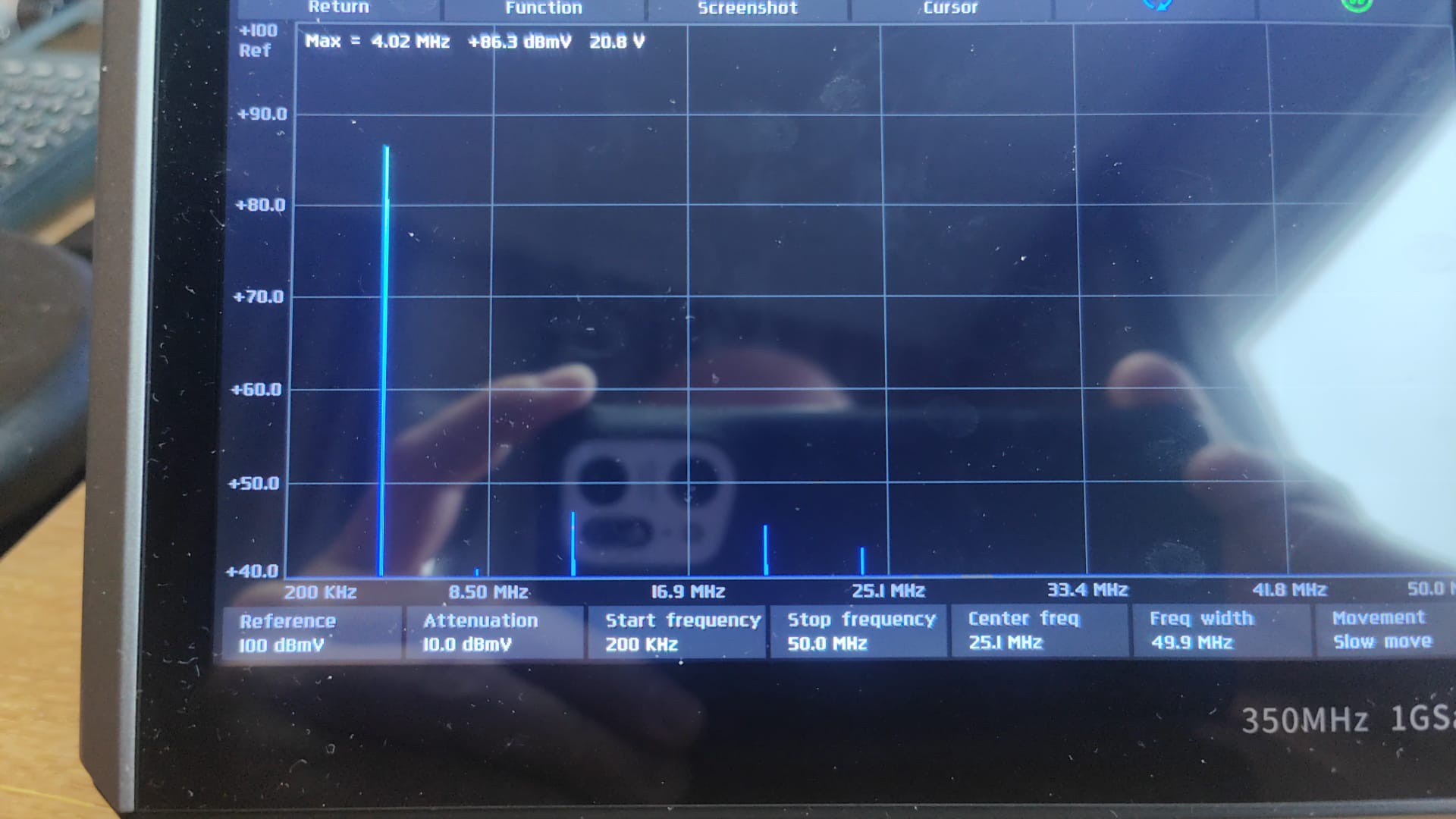
The 3rd harmonic is the strongest, it's about 40dB under the 4MHz signal, kind of ok, but I would like to know what's causing it. As we all know; profound truths are found by practicing the ancient art of datasheet-staring:...
Read more »