 electronicsworkshops
MP2307 5V to 24V Buck Converter
Introduction
If you've ever needed to step down a higher DC voltage say, from a 12V or 24V source down to a clean, stable 5V rail without burning power as heat, a linear regulator just won't cut it efficiently. That's where the MP2307 buck converter comes in. In this project blog, I'll walk through exactly how I designed, built, and tested a 5V output buck converter using the MP2307 switching regulator IC covering the schematic, component selection math, PCB considerations, and bench-tested performance numbers.
For Full Project
https://electronicsworkshops.com/mp2307-5v-buck-converter-a-complete-project-build-guide/
What Is the MP2307?
The MP2307 is a monolithic synchronous buck regulator manufactured by Monolithic Power Systems (MPS). It integrates a pair of low-resistance 100mΩ power MOSFETs on-chip, which is what allows it to deliver up to 3A of continuous load current across a wide input voltage range — without needing an external Schottky diode. That low on-resistance is a big part of why this chip runs cool and efficient even at full load.
Key headline specs that make it a popular choice for hobbyist and professional power supply projects alike:
Input voltage range: 4.75V to 23V
Output current: up to 3A continuous
Integrated MOSFETs: 100mΩ on-resistance, synchronous (high-side + low-side) — no external diode needed
Fixed switching frequency: 340kHz
Output voltage: adjustable via a resistor divider (down to 0.925V reference), or fixed-output variants are available
Package: typically available in SO8 / TSOT23-8 style packages, useful for moderately compact builds
Because the MOSFETs are synchronous and low-resistance, conduction losses stay low and efficiency commonly lands in the 90–95% range depending on input/output voltage and load — a massive improvement over a linear regulator, which simply dissipates the voltage difference as heat.
Why Build a Buck Converter Instead of Using a Linear Regulator
This is usually the first question that comes up, so let's settle it with the math. Say you have a 12V input and need 5V at 2A output.
Linear regulator (e.g., LM7805): Power dissipated = (Vin − Vout) × Iout = (12 − 5) × 2 = 14W wasted as heat
MP2307 buck converter at ~92% efficiency: Output power = 5 × 2 = 10W. Input power ≈ 10 / 0.92 ≈ 10.87W. Power lost ≈ 0.87W
That's the difference between needing a large heatsink and fan versus a small IC that barely gets warm. For battery-powered or thermally constrained projects, this isn't optional — it's essential.
Project Goals and Specifications
Circuit Design and Schematic
The MP2307 reference application circuit follows a classic synchronous buck topology. The core building blocks are:
Input bulk capacitor (Cin) — buffers the input rail and supplies the pulsed current the switching MOSFET demands.
MP2307 IC — handles switching, current limiting, soft-start, and thermal shutdown internally.
Inductor (L1) — stores and releases energy each switching cycle, smoothing the pulsed switch-node voltage into a DC current.
Output capacitor (Cout) — filters the inductor ripple current into a clean DC output voltage.
Feedback resistor divider (R1, R2) — sets the output voltage by feeding a scaled-down version of Vout back to the FB pin, compared against the internal 0.925V reference.
Compensation network (Rc, Cc) — stabilizes the control loop, since the MP2307 uses voltage-mode control with external compensation.
Bootstrap capacitor (Cboot) — drives the high-side MOSFET gate above the input rail.
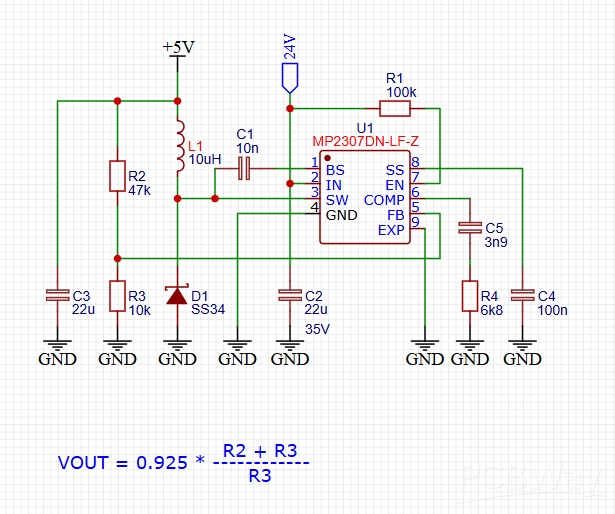
The signal flow is straightforward: input power enters at Cin, gets chopped by the internal high-side/low-side MOSFETs at 340kHz, smoothed by the L1–Cout filter, and the resulting DC output is sampled by the feedback divider to keep the loop regulated at exactly 5V.
The MP2307 reference application circuit follows a classic synchronous buck topology. The core building blocks are:
Input bulk capacitor (Cin) — buffers the input rail and supplies the pulsed current the switching MOSFET demands.
MP2307 IC — handles switching, current limiting, soft-start, and thermal shutdown internally.
Inductor (L1) — stores and releases energy each switching cycle, smoothing the pulsed switch-node voltage into a DC current.
Output capacitor (Cout) — filters the inductor ripple current into a clean DC output voltage.
Feedback resistor divider (R1, R2) — sets the output voltage by feeding a scaled-down version of Vout back to the FB pin, compared against the internal 0.925V reference.
Compensation network (Rc, Cc) — stabilizes the control loop, since the MP2307 uses voltage-mode control with external compensation.
Bootstrap capacitor (Cboot) — drives the high-side MOSFET gate above the input rail.
The signal flow is straightforward: input power enters at Cin, gets chopped by the internal high-side/low-side MOSFETs at 340kHz, smoothed by the L1–Cout filter, and the resulting DC output is sampled by the feedback divider to keep the loop regulated at exactly 5V.
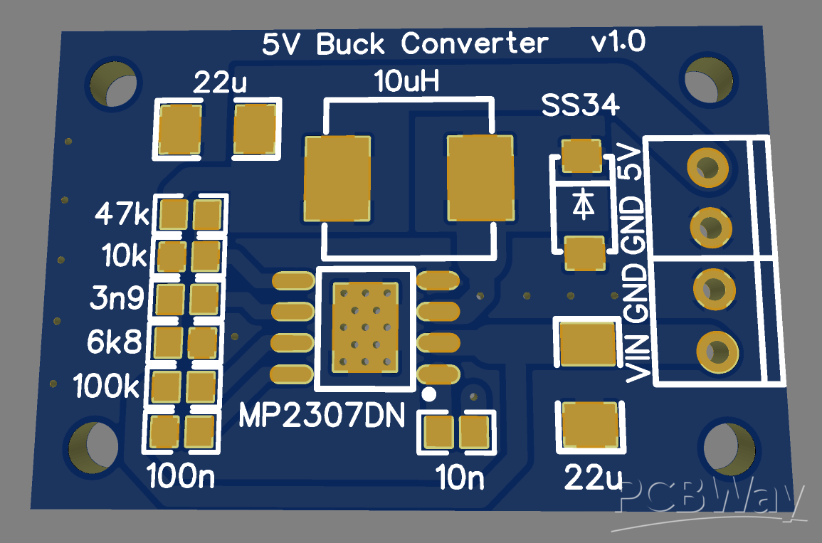
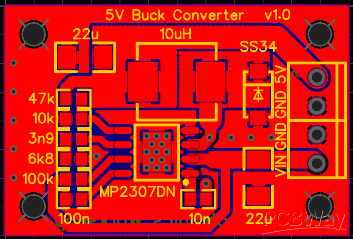
PCB Image
Order Directly from PCB WAY
I have already uploaded all these required manufacturing files in PCBWAY website. You can easily go to the below link and place you order, and get your Own Home Automation PCB manufactured from one of the best pcb manufacturer PCBWAY
Conclusion
The MP2307 remains one of the most practical chips for a 5V buck converter project thanks to its integrated synchronous MOSFETs, simple external component count, and forgiving design margins. With careful attention to inductor selection, output capacitor ESR, and PCB layout — particularly around the switch node and feedback trace — it's straightforward to hit 90%+ efficiency in a compact footprint.
If you're working on a similar power supply build, the calculations above (feedback divider, inductor sizing, and capacitor selection) apply broadly to most MP2307-based designs, not just this specific 5V/2A target — adjust the divider ratio and component values for your own input/output requirements.
For Full Project
https://electronicsworkshops.com/mp2307-5v-buck-converter-a-complete-project-build-guide/
Best Electronics Calculator
Numerical Calculator offers the best collection of electronics calculators including Ohm's Law, PCB Trace Width, Voltage Drop, LED Resistor, Battery, Power, and Circuit Design tools - all in one place. Numerical Calculator The Ultimate Electronics Calculation Platform for Engineers, Technicians, Students, and PCB Designers. Fast, Accurate, and Free!
https://numericalcalculator.com/