 lion mclionhead
An adjustable 5-12V power supply with 10A would be quite expensive & inefficient, so it almost has to run on a fixed 12V, adjusting the voltage in the transformer stage. The low battery voltage cutoff still has to be left out, to allow it to start a motor. It still cuts out below 5V, but it seems to be just resilient enough to start a motor when it was hopeless before.
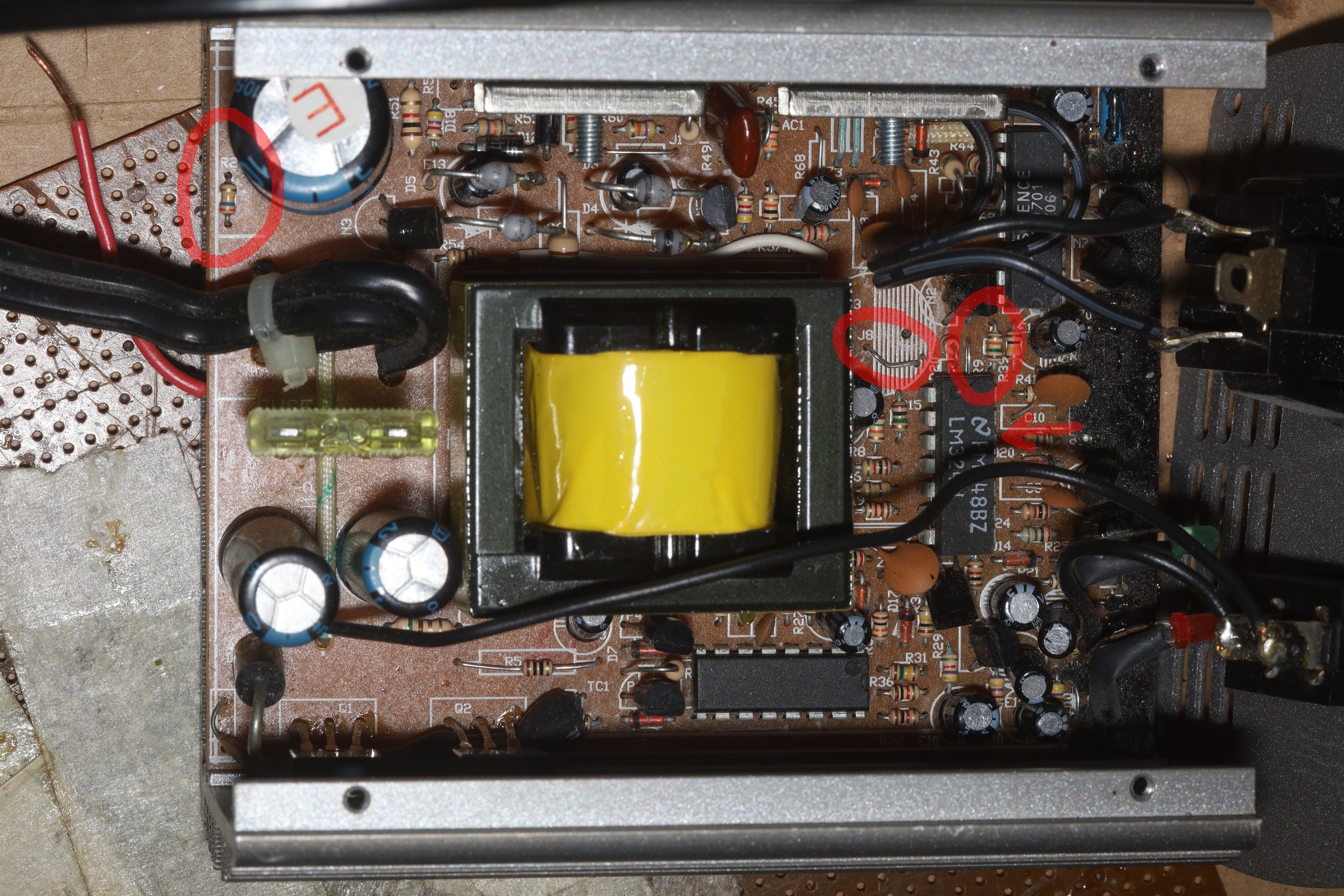
The feedback resistor network is R2 & R9. R2 360k & R9 15k divide 140V DC roughly down to 5V. Reducing R2 or increasing R9 reduces the output voltage. Then it goes into the LM324. A digital pot in series with R9 could do the job. Replacing R9 with a digital pot would risk blowing it up. Helas, there's now a risk of stalling the motor if the pot glitches. It almost needs to start at full power, then ramp down.
So it needs 5.5V for the digital pot & offboard micro, 10V to overclock the YC9701. Since the inverted waveform is going to be fixed, the battery voltage needs to be limited to limit the inverted RMS voltage.
In the worst case, the offboard micro could generate the square wave itself. That would allow it to run at 50Hz, though the frequency comes from an RC circuit near the YC9701. The final question is the user interface. It probably needs to capture IR codes & store the setting in flash. The remote would have up & down but not presets. It probably needs an indication of the voltage setting.
Of course, another long desired feature was remote power off. That would be done by shutting off the 12V side with another MOSFET.
Discussions
Become a Hackaday.io Member
Create an account to leave a comment. Already have an account? Log In.