 lion mclionhead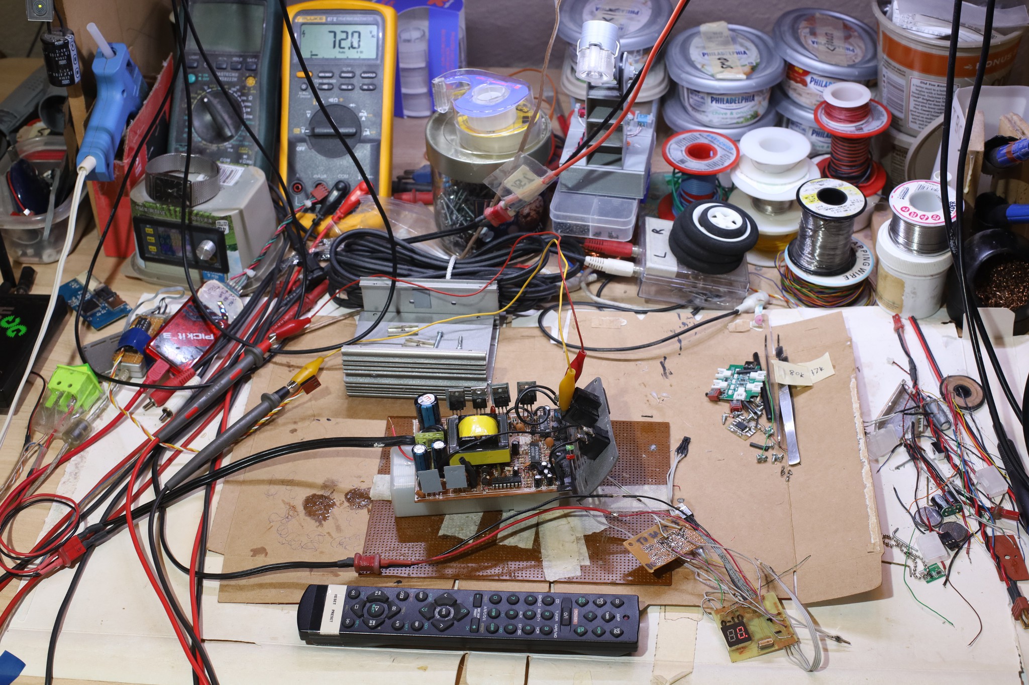
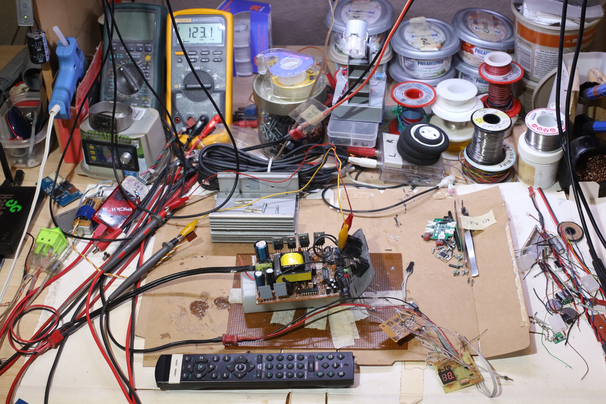
Got a full voltage adjustment & user interface working with the AD5231 replacing the R9 feedback resistor & an IR remote. On 12.5V no load, it outputs 72-123V AC. Channel -/+ dial in 10 voltage settings. Mute toggles the power on & off by toggling the waveform generator. The standby power with no waveform is 2W. R9 is configured to go from 15k - 30k.
If the AD5231 is unpowered, it's an open circuit & the inverter goes to 123V. The inverter has a clamping diode which keeps the feedback resistor from blowing up. R9 is clamped to 15k minimum.
The maximum output voltage highly depends on the battery voltage & the load. It goes up to 126V for a 13V battery, but is clamped at 126V above 13V in. The minimum output voltage stays 72 for all battery voltages. The resistance range would have to be dialed in with the blower loading it & the final battery voltage. Lions expect to feed it 14V to try to improve the efficiency.
It's unlikely a voltage regulator for the brain side would improve matters.
The Mastech MS8222H reports 72-130V while the Fluke shows 72-126V.
--------------------------------------------------------------------------------------------------------
The LED lighting used the mighty Mean Well LRS-200-15 because it needed 15V 100W. It goes from 13.5-18V. The inverter goes to 16V before it blows up. It also needs a fan.
The LED lighting & inverter could both go in a power rack, but the LED lighting needs a switched input.
Discussions
Become a Hackaday.io Member
Create an account to leave a comment. Already have an account? Log In.