 lion mclionhead
It became clear that it needs to switch to manes voltage for the maximum power setting with some kind of relay. It's not a piece of test equipment but going to be powering a blower all day, normally at maximum. Not just the live but the neutral has to be switched, because inverter neutral is live. To avoid putting negative voltage & back EMF on the MOSFETs, it needed an open circuit state for a time between selecting the inverter & manes so that meant 4 relays.
Another idea was to have a way to plug in a battery between the Meanwell & the inverter. That would allow it to still run as a conventional inverter or power the blower without manes, for a short time. This would need a manual switch.
Also, given the new need for relays, decided to rebuild the hacker board with vintage components, for vintage appeal & to get rid of some parts. It was slow going, in the old days.
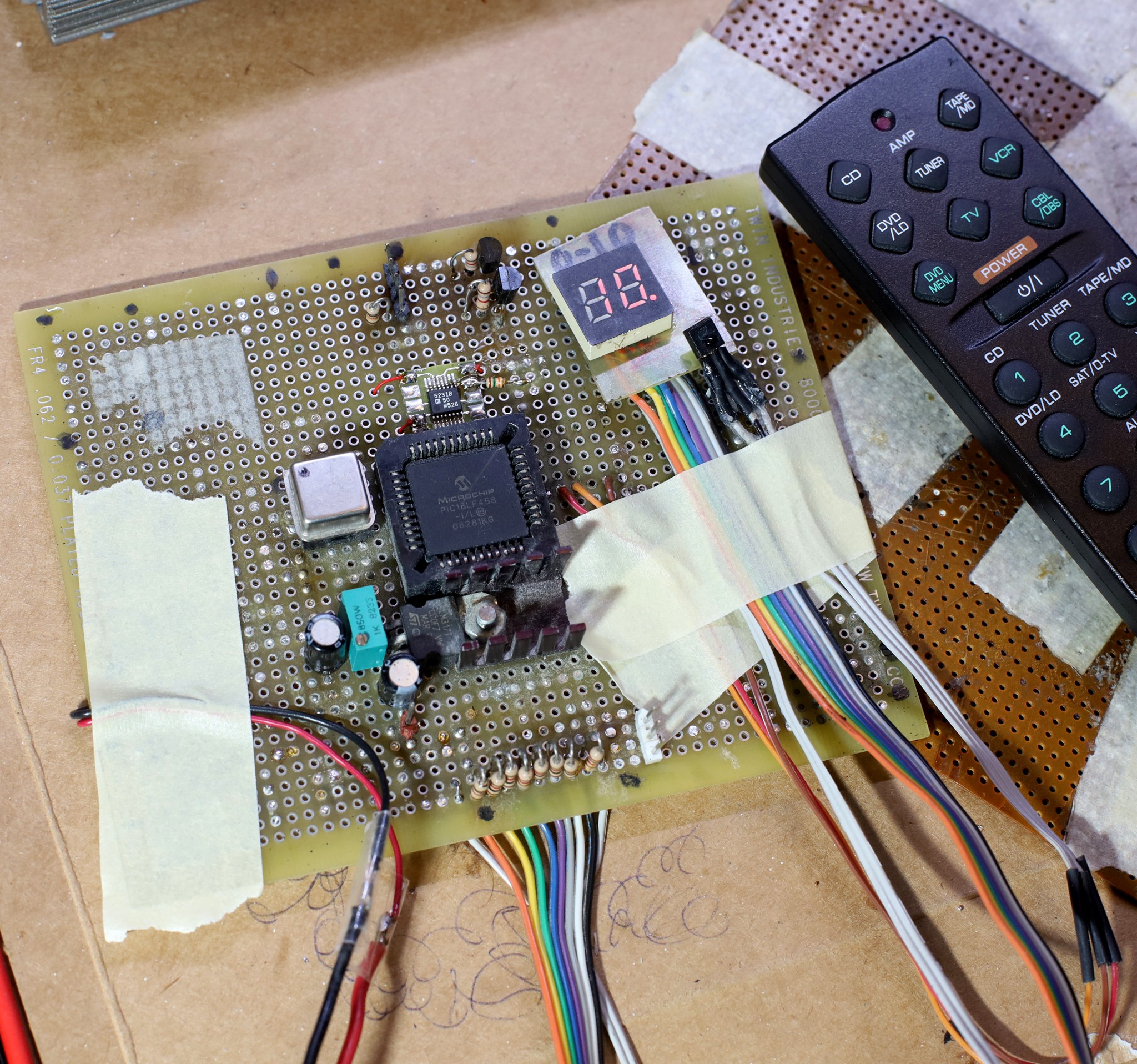
This board dated back to Aug 2008, went through many crashes, hopefully won't be reworked again. The LED panel dated back to 1997.
It would go in a big ass coroplastic/PLA rack enclosure. It would need a thermostat controlled fan.
At this point, it started becoming clear how overdone this was, compared to a simple dimmer switch. A remote controlled dimmer switch could have used a servo & cost nothing. It would probably have been just as noisy as the inverter.
There's a chance increasing the frequency could reduce the noise. Commercial inverters make real sine waves with PWM. Then they have a very large LC filter to smooth the manes voltage side. It's a tradeoff between efficiency & noise. Lions don't have the budget to create a fully functional frequency & voltage interface. A voltage indicator from 0-10 is as good as it gets.
----------------------------------------
Tearing down a newer Rhino 400W inverter, it would be a more destructive process to remove the brownout protection & synthesize a custom waveform, but it could be done with a lot of effort. The transformer driver would have to be completely replaced.
Reviewing modern options, square wave inverters below 1kw are now few & far between. Cheaper off grid solutions have driven the market to true sine wave, grid replacements. No-one tears them down anymore, but presumably they all have a big LC filter.
-----------------------------------------------------------------------------------------------
EG8010 notes:
Everyone was building sub kW sine wave inverters from the same EG8010 widget board, years ago. All those projects have bit rotted, because of the liability.
https://www.amazon.com/dp/B07T7VY756
That creates the sine wave with PWM but doesn't perform the voltage boost. It has full frequency & voltage control by adjusting a feedback resistor.
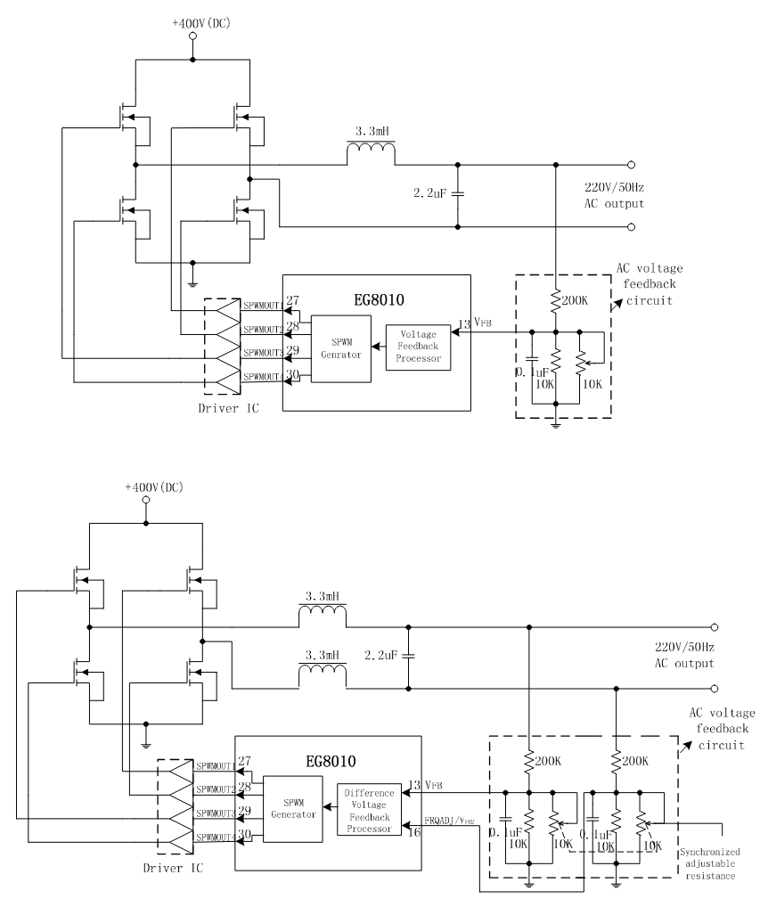
The datasheet shows an example LC circuit for a unipolar & bipolar configuration. In unipolar mode, 1/2 of the bridge gets PWM while the other half gets DC. In bipolar mode, the full bridge gets PWM. Bipolar mode resulted in better filtering. Fully adjustable frequency was only possible in unipolar mode. It had a serial protocol for setting the desired feedback voltage & the frequency range in unipolar mode. The PWM ran at 24khz, just above lion hearing. A blower could be noisy enough to negate the square wave humming.
Note: a true sine wave hack wouldn't work with the Jazz 150 since it would have to peak at 170V. It probably explodes much beyond 140V.
Discussions
Become a Hackaday.io Member
Create an account to leave a comment. Already have an account? Log In.