 Eviscerate Core
Gimbal motion demonstration:
A stereoscopic 3-axis camera gimbal controlled with an Oculus Rift.
Already have an account? Log in.
To make the experience fit your profile, pick a username and tell us what interests you.
Gimbal motion demonstration:
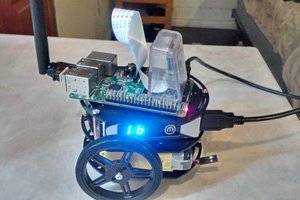
In the previous demo videos of the gimbal, I was using a separate platform (PIC32) to operate the servos. To consolidate resources, and simplify design, I wanted to transfer the servo operation to one of the Raspberry Pis already on the gimbal.
A few months ago, I experimented with using the Raspberry Pi's IO pins to run servos. The code I put together for that can be seen HERE. I'm using IO pins 4, 17, and 18 to operate the X, Y, and Z axis servos, respectively. I used protoboard to create a simple breakout board between the Raspberry Pi and the servos. External power was used for the servos. Here is the initial design sketch I put together:

In the final design, I decided to add a power LED and status LEDs for each of the servo channels. I also flipped the servo connectors as compared to the above sketch. Here is the finished board with everything connected:

Right now the software is converting the tracking position for each servo into an 8-bit value to transport from the Oculus Rift to the Raspberry Pi. The result of this is somewhat choppy motion in the servos, so I will be switching to use 16-bit values next time I touch the software. Besides that, it's working well and I'm very happy with the result. The next step is to figure out how to mount this breakout board to the gimbal.
Over the next few weeks I will be adding updates to this project. My first goal will be to switch servo control over to one of the Raspberry Pis.
 Brenda Armour
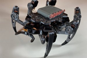
 Max.K
Max.K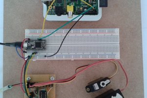
 Christoph
 danielmcgraw