 Connor May
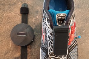
The Unit
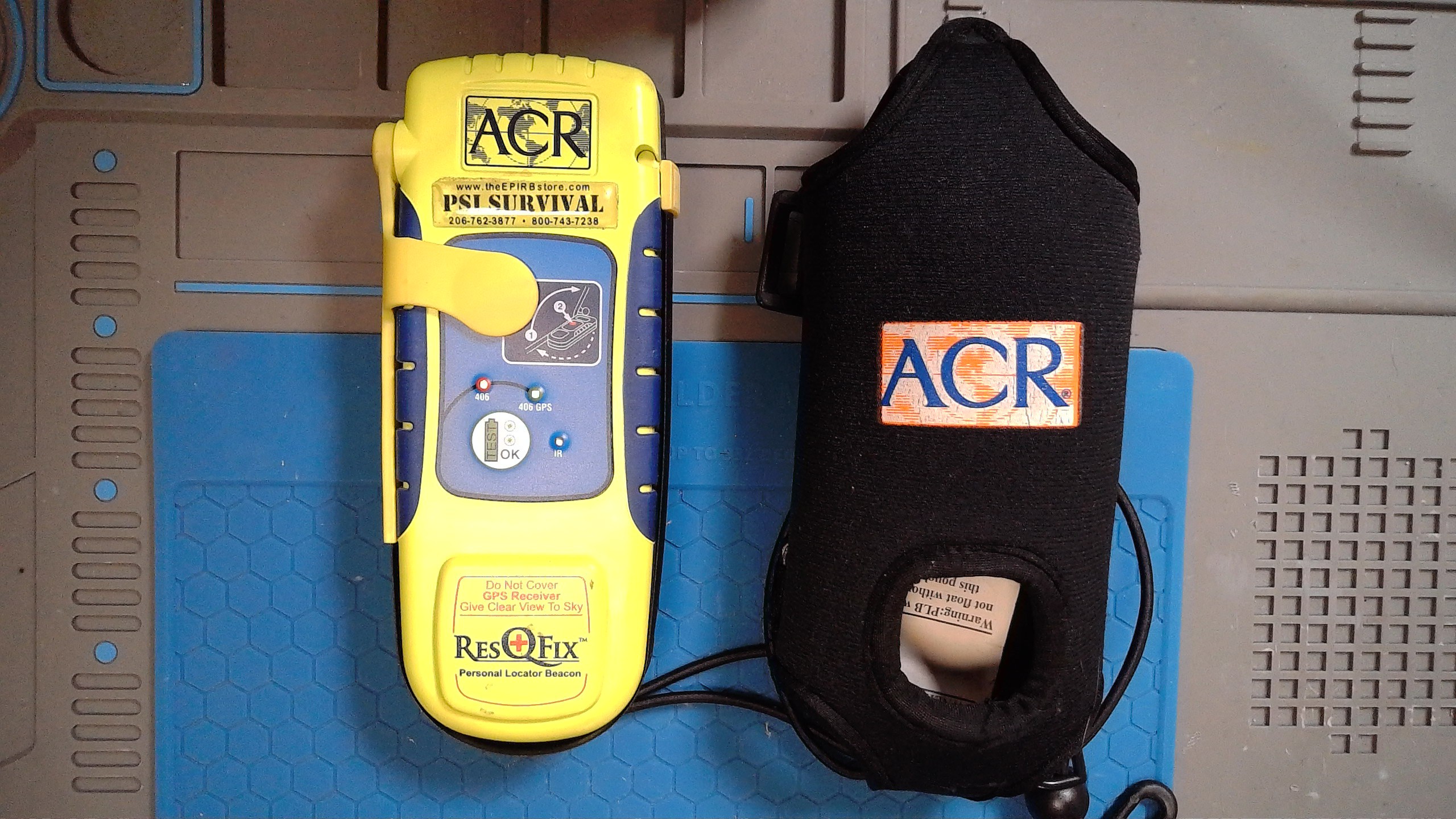
ACR Electronics ResQFix, badged "PSI Survival" (theEPIRBstore.com), FCC ID B66ACR-PLB-300. Neon green polycarbonate case with the typical PLB layout: fold-out antenna, manual activation lever under a neon green guard, and a status LED cluster labeled 406, 406 GPS, TEST/OK, and IR. The "Do Not Cover GPS Receiver Give Clear View To Sky" warning is molded directly into the bottom of the case over the GPS patch antenna. Came in a black nylon ACR-branded floating pouch with a lanyard.
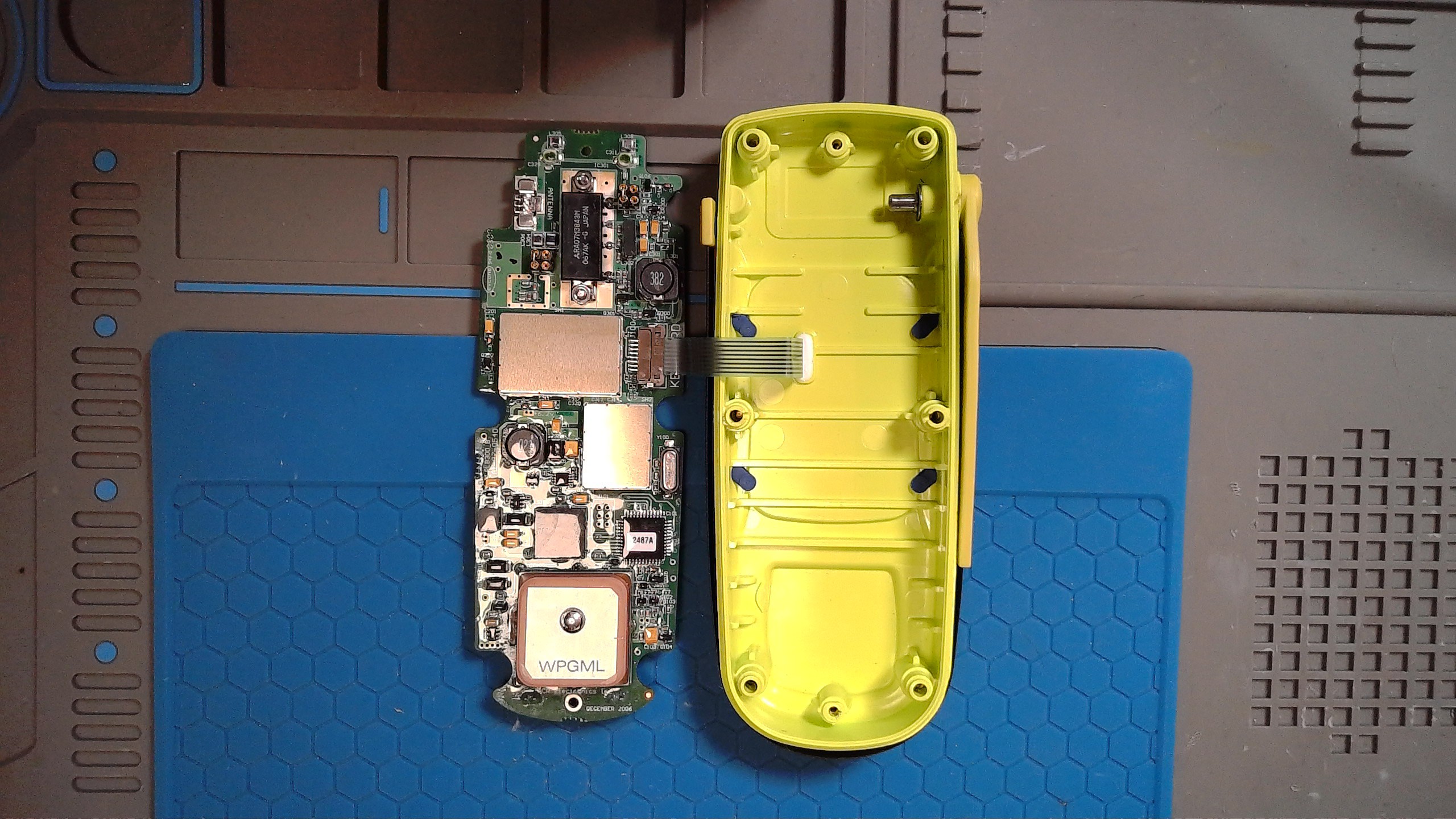
Opening It Up
No ultrasonic welds. Six Phillips screws around the case perimeter hold the front half to the rear battery cover. Once those are out, it splits right open. Each of the 6 screws has an O-ring as well
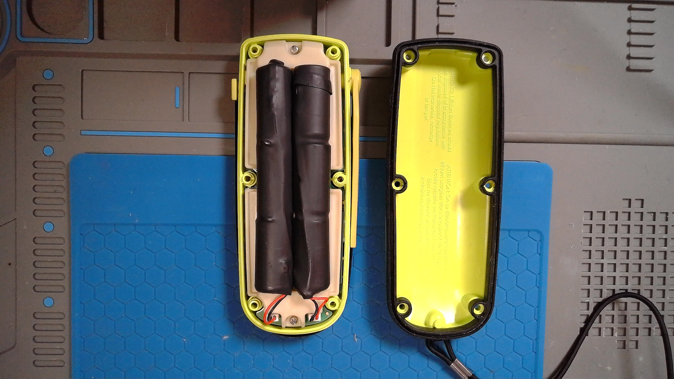
There's a second inner cover screwed down separately over just the battery bay, so the battery compartment stays isolated from the rest of the electronics even with the outer case open. Two cylindrical lithium packs, wrapped in black heat-shrink, sit in a molded plastic cradle, each on its own 2-pin JST-style connector.
The Battery
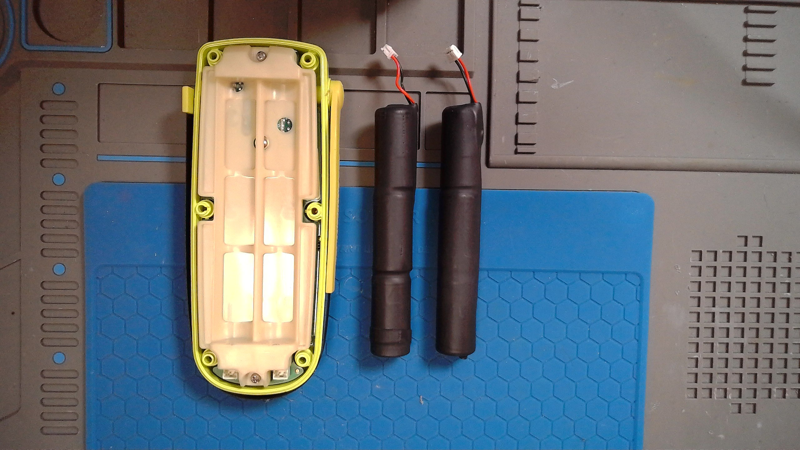
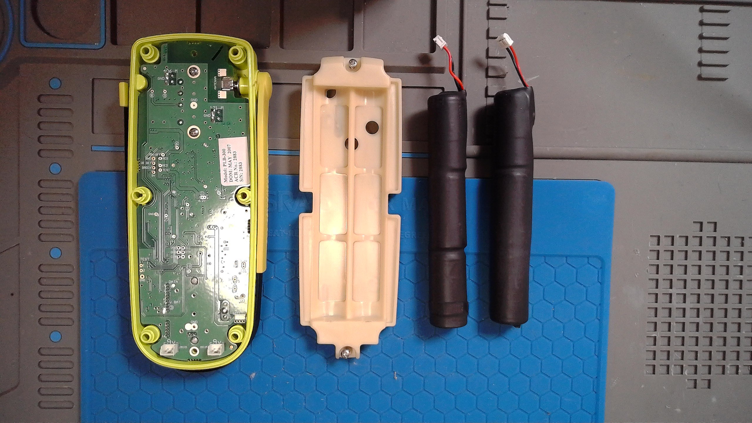
Two separate packs, independently connectorized. Board sticker reads:
Model: PLB-300
DOM: May 2007
ACR No.: 2883
S/N: 2883
Manufactured in May 2007. Old beacon.
Main Board Layout
The silkscreen does most of the talking here. Working down the board:
- Top section: 406M and 121M pads with GND references. These are almost certainly RF test/tuning points for the 406 MHz distress transmitter and 121.5 MHz homing beacon, sitting right next to the spring-loaded ANTENNA contact that mates with the fold-out whip.
- Middle section: test pad cluster labeled On/Off, RES, IR DET, Red, Green, Test. Self-test and LED driver interface, matching the TEST/OK and IR indicators on the front face.
- Lower section: DATA pads, a U BAT connector, 4-pin BATT-SW header, and two separate 9V test points, one per battery pack.
The RF Power Stage
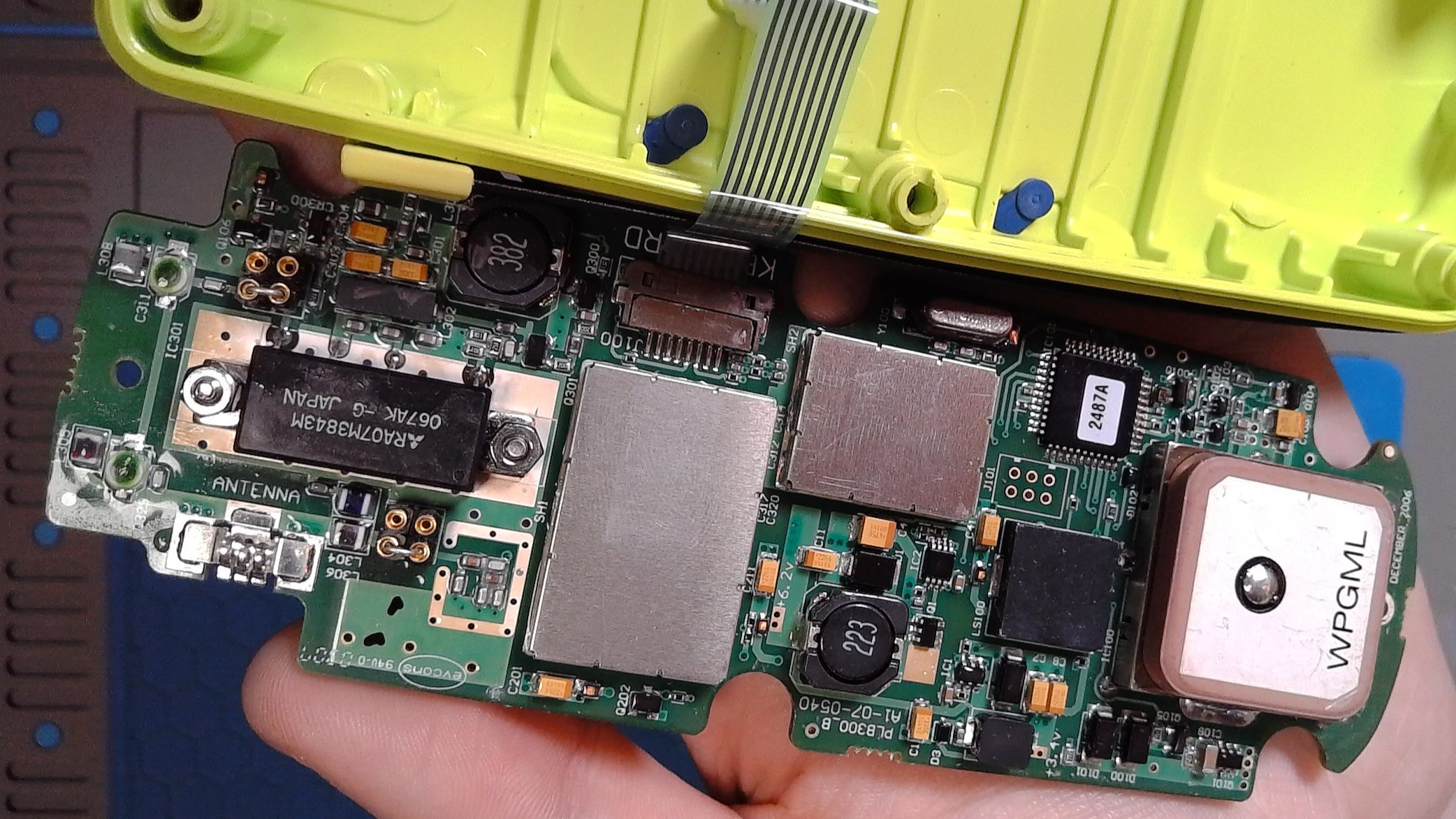
The transmit PA is a Mitsubishi RA07M3843M, a 378-430 MHz, 7W, 2-stage silicon RF power module originally designed for portable radio. That range covers the 406.0-406.1 MHz COSPAS-SARSAT distress band comfortably, and 7W output is right where you'd expect for a 406 MHz PLB. It's mounted on a solid copper pour for heatsinking, with the ANTENNA trace silkscreened right next to it, feeding out toward the antenna contact. The surrounding passive components look like the output matching/filter network between the PA and the antenna.
The GPS Daughtercard
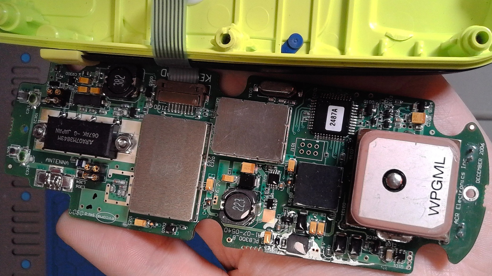
- Ceramic patch antenna marked WPGML, date code DECEMBER 2006
- Shielded IC can next to the patch (GPS receiver, likely SiRF or u-blox era from 2006)
- QFP IC marked 2487A (unidentified so far)
- Crystal Y100 for GPS clock reference
- Local rails labeled +6.2V and +3.4V
 Chad
Chad
 Mike Szczys
 Kinetic Labs
 Danny Andreev