 Alireza Noferesti
The idea came from a real need in long-duration laboratory testing, where simply turning devices ON/OFF is not enough. In many test setups, multiple instruments, power supplies, motors, heaters, optical equipment, or automated fixtures may be connected to the same UPS or power rail.
While a UPS is useful for backup power, it usually cannot monitor or disconnect each output independently. If one connected device draws a high inrush current, creates a surge, or behaves abnormally, other devices on the same power source can be affected.
The Noora Power Monitoring Switch was designed to address this missing layer between the UPS and the connected equipment. It combines four independently controlled AC output channels with real-time voltage and current monitoring, allowing each socket to be switched, monitored, and protected independently.
Some of the main features:
- 4 independently controlled AC output sockets
- Voltage and current monitoring
- True-RMS current measurement per channel
- True-RMS, Mean, and Peak-to-Peak voltage measurement
- User-selectable measurement window based on AC half-cycles
- Fast RMS mode for surge protection and fast response
- Configurable surge protection per channel
- USB interface
- LabVIEW modules and control/monitoring software
- Windows executable software supported via LabVIEW Runtime Engine
- Expandable architecture using loop/network connection for multi-unit setups
One of the parts we focused on was half-cycle-based monitoring. Instead of only measuring slow averaged values, the device can calculate RMS values over a user-defined number of half-cycles. This makes it useful for detecting short events such as inrush current, brownouts, voltage transients, and unusual load behaviour during automated tests.
Each current channel also has configurable surge protection. For example, the user can define allowed current and duration values during startup and after startup. If the measured value exceeds the configured limits, the output relay can be disabled automatically.
We originally designed this for internal and industrial lab use, but we are now trying to understand whether there is broader interest from hardware developers, test engineers, research labs, and automation users.
Potential use cases include:
- Long-duration device testing
- Automated test benches
- Semiconductor or optical lab equipment
- Monitoring power behaviour of multiple instruments
- Detecting abnormal current or voltage events
- Protecting sensitive equipment from unexpected load behaviour
- Remote power control with measurement feedback
This is not intended to replace a full oscilloscope or a precision power analyser. The goal is to provide a compact multi-channel power control and monitoring device that can sit inside a test setup and continuously watch what is happening on each AC output.
We are considering whether it makes sense to prepare a more public-facing version of this device, possibly through a small production run or crowdfunding campaign.
Channel-Specific Current Cards & Shared Voltage Card — How Monitoring Works:
Each Power Monitoring Switch unit comes with one dedicated current measurement card for each channel or socket. However, regardless of the number of channels, every Power Switch is equipped with only one voltage measurement card, which monitors and controls the voltage for all channels.
⚡ Voltage Card Features:
- Accuracy: 0.12 volts at 250V RMS
- Measurement speed: Up to 50 ksps
- Supports the following voltage measurements:
- True-RMS Voltage
- Mean Voltage
- Peak-to-Peak Voltage
- Isolation: Up to 4000 volts
- User-defined measurement window from 1/2 cycle to 60 cycles for True-RMS, Mean, and Peak-to-Peak voltage
- Ability to control output sockets separately using voltage card control functions
- Detects, monitors, and reports:
- Voltage sags
- Surges
- Spikes
- Transients
- Harmonics
- Electrical noise
- Blackouts
over a user-defined window of 1/2 to 60 cycles
⚡ Current Card Features:
- Accuracy: 0.03 amps
- Isolation up to 4000 volts
- Supports measurement speeds up to 10 ksps
- Equipped with a fast True-RMS measurement mode
- Over-current sensor transient tolerance: 100 ms pulse, 100 A
- True-RMS current measurement configurable from 1/2 to 60 cycles (user-defined)
- Provides independent socket control using dedicated current card functions
- Built-in surge protection with adjustable timing for both continuous current and peak current events
- Surge protection handles up to 15 amps with a maximum duration of 2 seconds, featuring 1 ms precision.
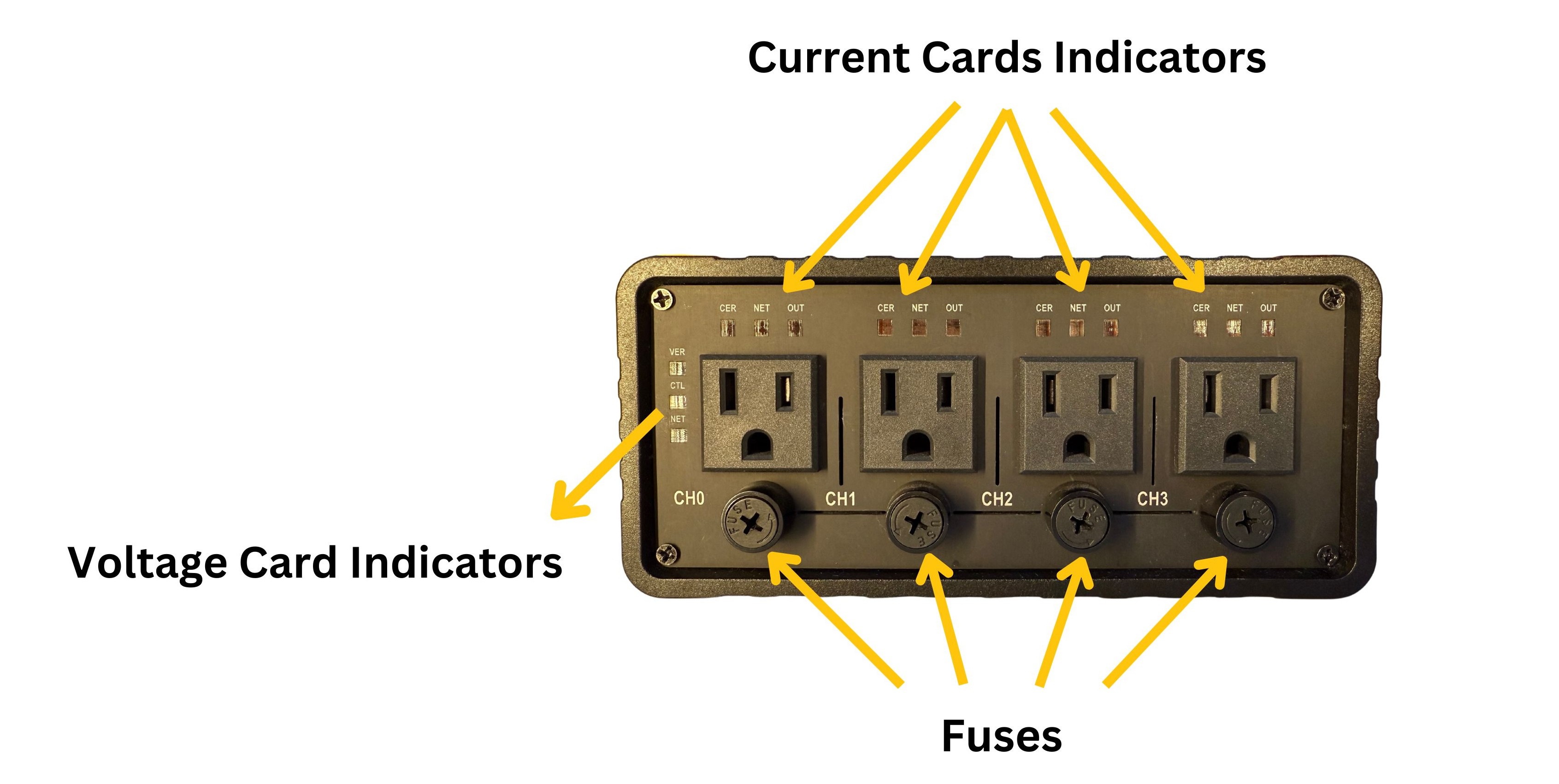
How Noora P.M.S. Works:
The simplest and fastest way to get started with the Power Switch:
- Connect the Power Switch’s power cable.
- Connect the USB cable between the Power Switch and your computer.
- Plug the device you want to monitor into one of the Power Switch sockets, and activate surge protection if needed.
- Open one of the provided software tools to begin monitoring and controlling the Power Switch.
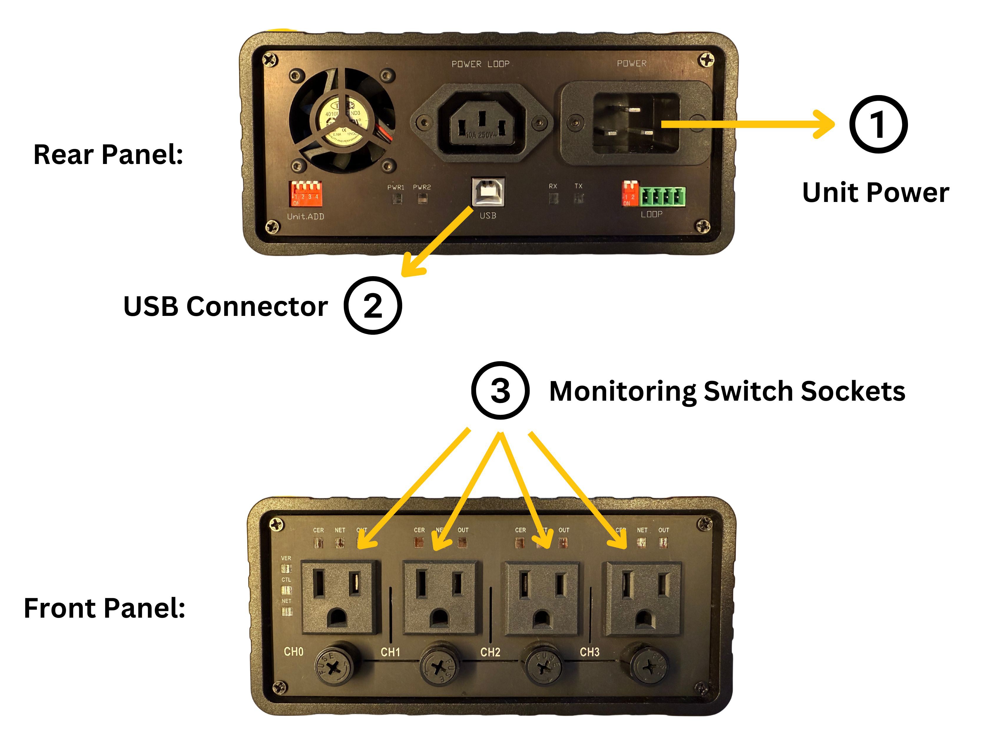
To operate the Power Switch and fully utilize its capabilities, we provide three dedicated software tools:
- Channel Control & Monitoring
- Voltage and Current Control
- Voltage and Current Monitoring
The software packages include LabVIEW compatibility and also support Windows.
1- Channel Control & Monitoring:
This software lets you independently switch each channel On or Off, clear any errors, and monitor both the AC voltage and current cards simultaneously — all within a single window. It offers a comprehensive view of live data logging, acting as your central dashboard for real-time system monitoring and control.

Please note that the number of channels available for configuration and status monitoring in the software corresponds to the number of channels on the Power Switch model you have selected. For example, if you choose the single-channel P.M.S., only the first channel’s current section will be accessible in this software.
By default, channel numbers — representing the power sockets — are labeled starting from zero. For example, CH0 corresponds to the first channel (first socket), and CH1 refers to the second channel. Likewise, the current cards are numbered starting from zero, meaning the current card for CH0 (first channel/socket) is assigned Slave Address 0.
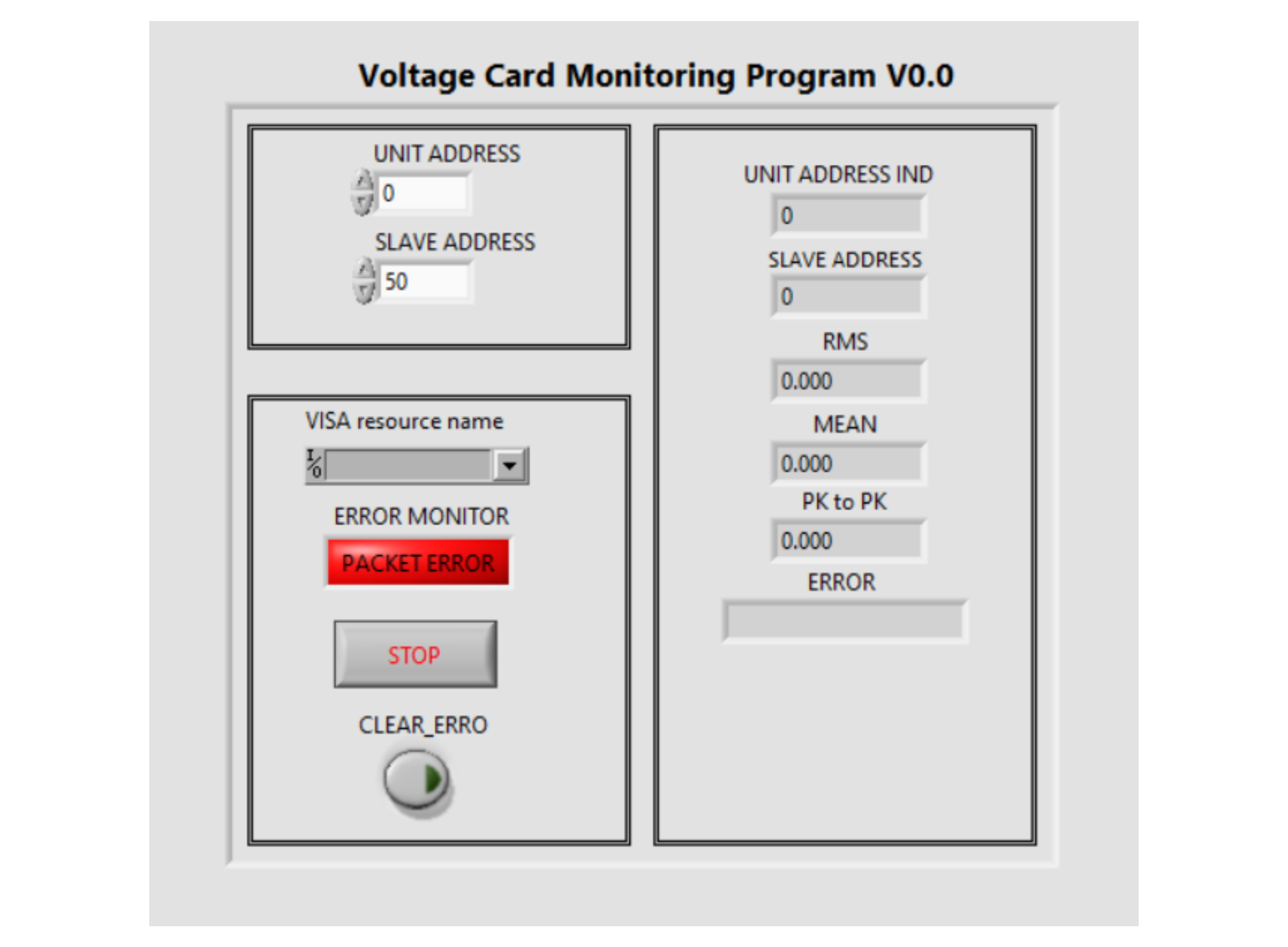
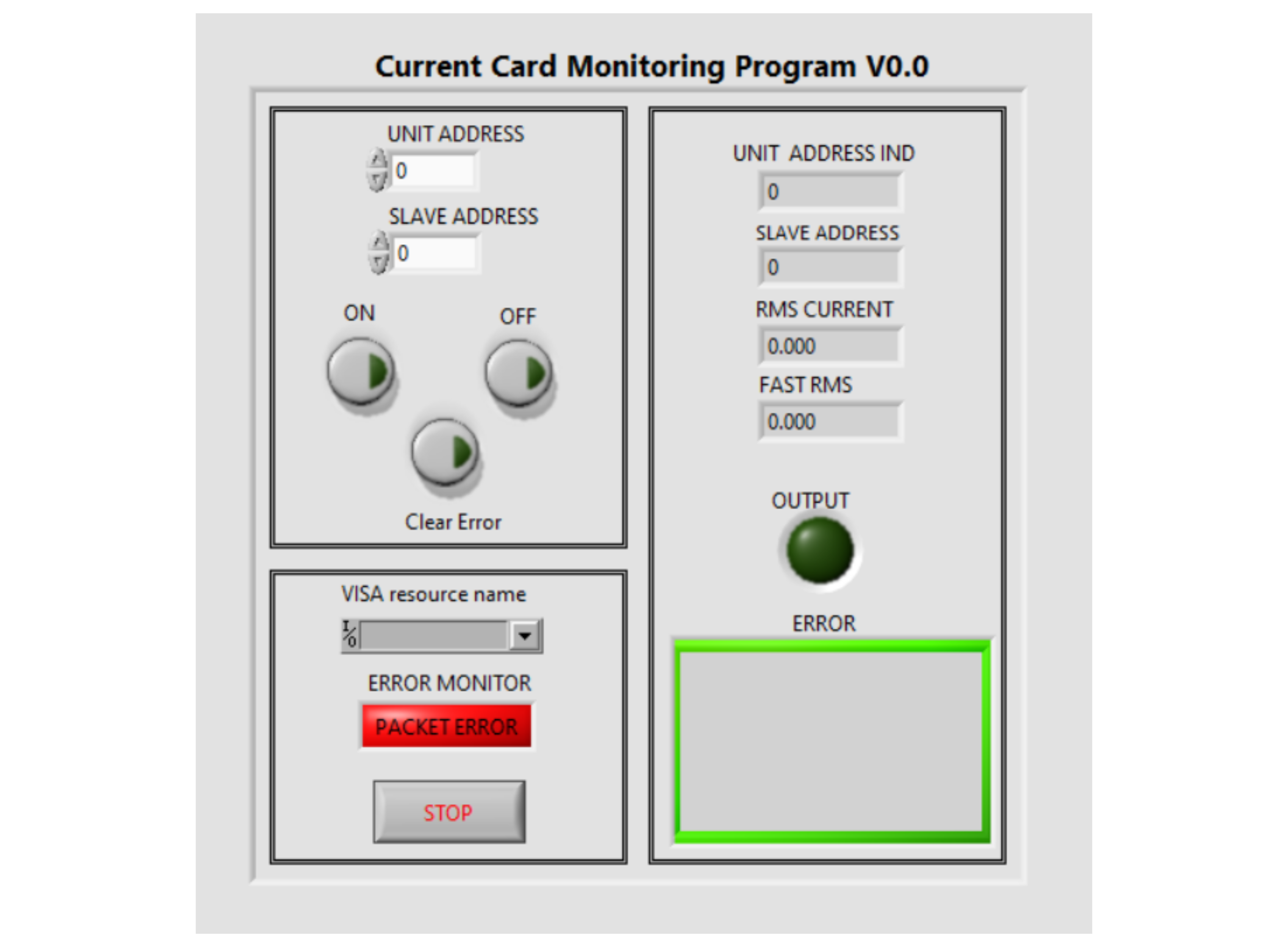
2- Voltage & Current Control
The Voltage Control and Current Control software (or panels) provide direct access to the settings of the voltage card and current cards. Each is divided into two main sections: the left section allows you to enter the desired configuration values, while the right section displays the currently applied settings from the device.
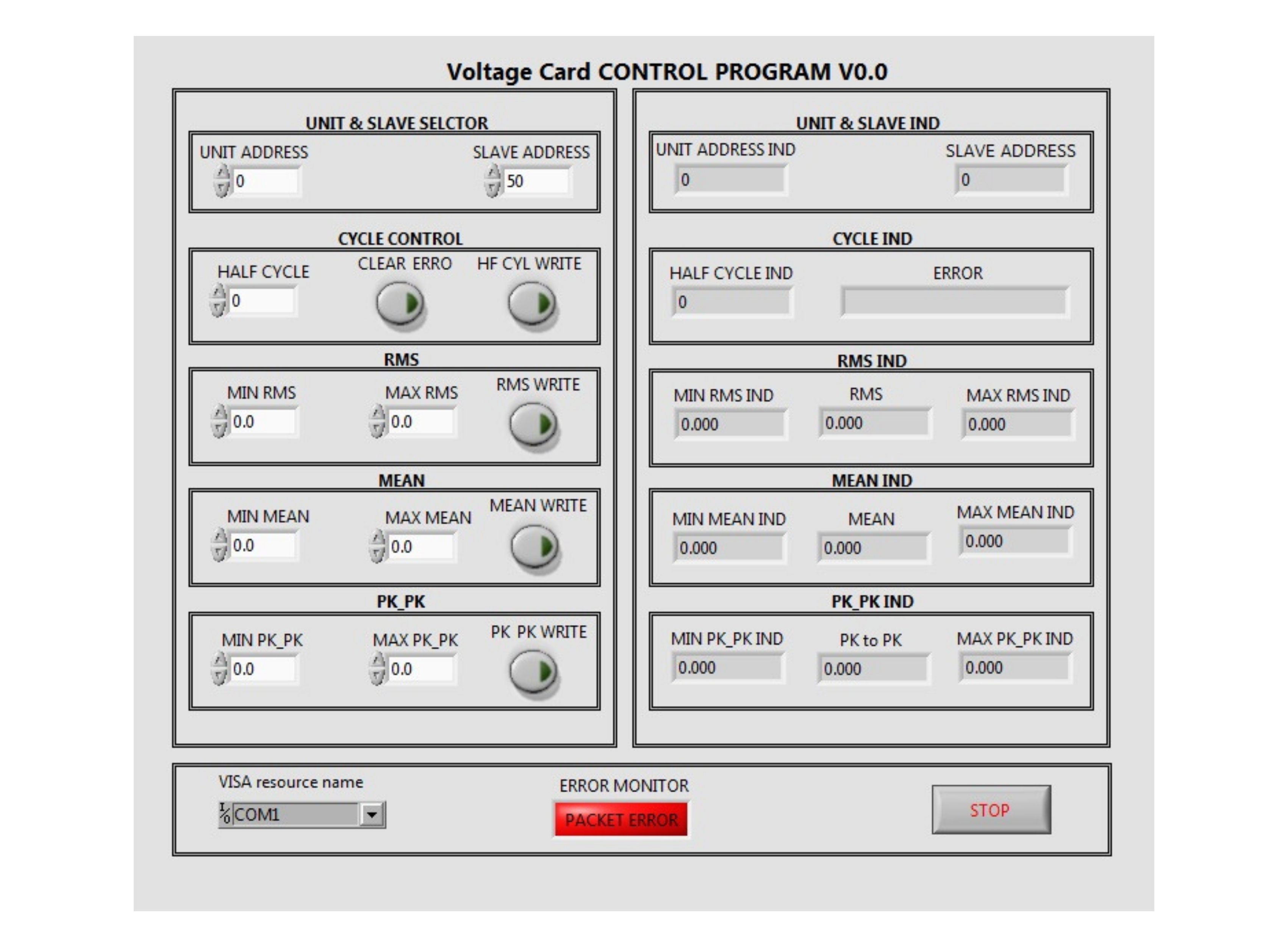
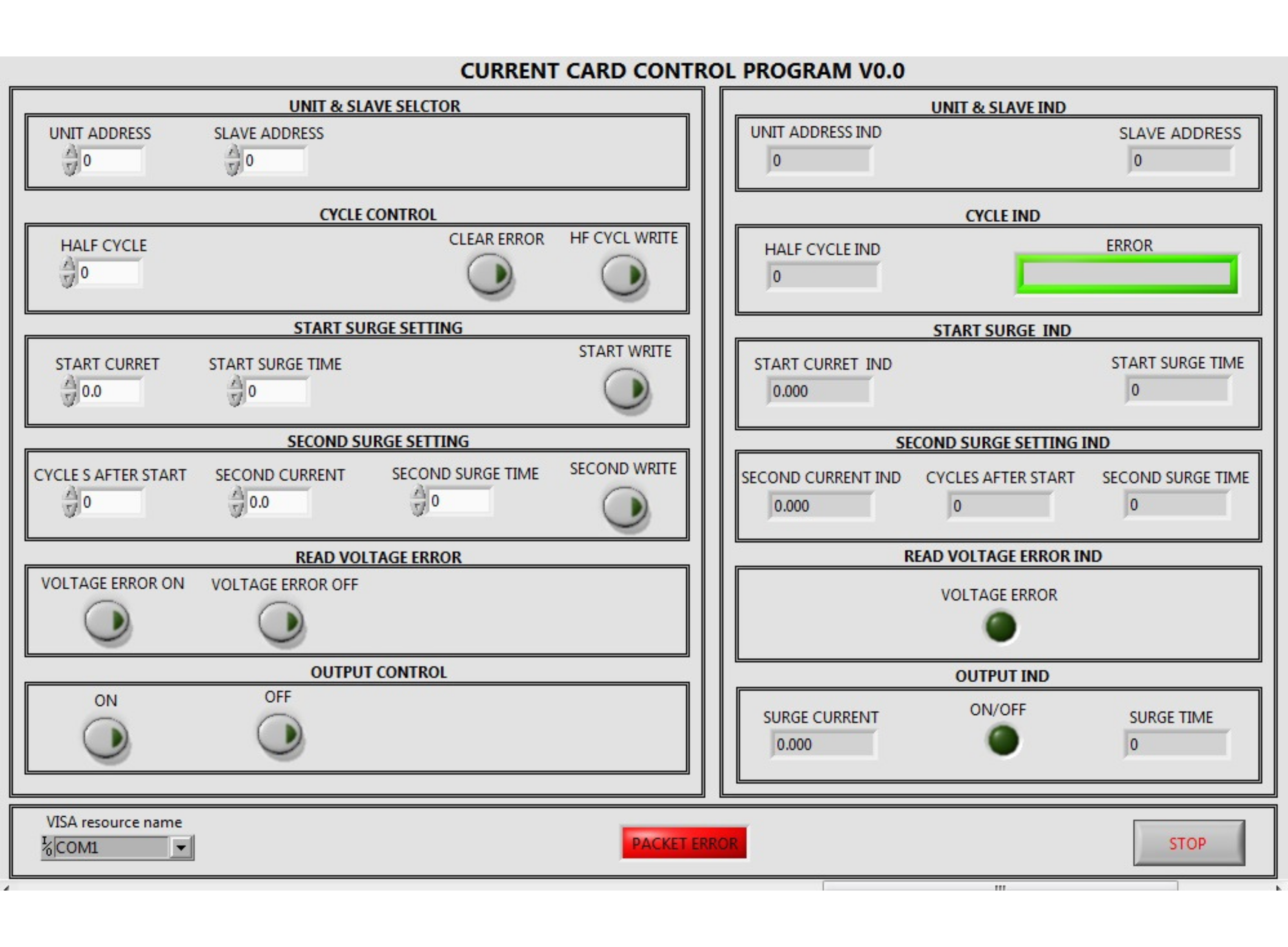
3- Voltage & Current Monitoring
You can monitor real-time voltage and current measurements directly through the software programs. The current control software also enables On/Off control for each channel.
50 Hz or 60 Hz
As previously mentioned, one of the valuable features of the Power Switch is its ability to calculate RMS current over user-defined half-cycle intervals. If this parameter is set to 1, the device will calculate RMS over a single voltage half-cycle. For reference, at an input power frequency of 60 Hz, there are 120 half-cycles per second; at 50 Hz, there are 100 half-cycles per second.
Multi-Unit Looping: From 4 Channels to 64 Channels
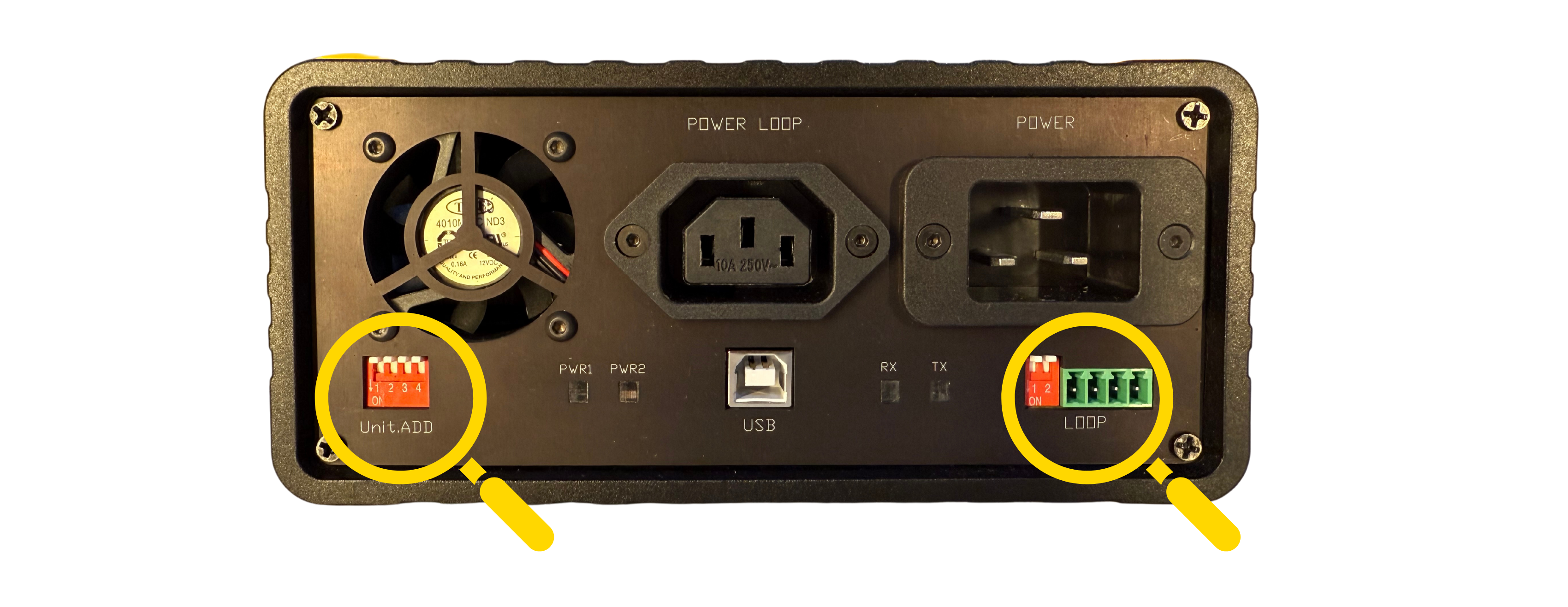
If more than four channels are required for monitoring and control, multiple Power Switch units can be looped together (using DIP switches on the rear panel) —up to 16 units in total. This creates a network of up to 64 channels or output sockets. By looping the Power Switches, you benefit from centralized control, significantly reducing the need for multiple USB connections. Only the first unit in the loop connects to the computer via USB, while the remaining units are linked through dedicated loop connectors, streamlining both setup and management.
Thanks — I’d love to hear your thoughts.