 Tony Goacher
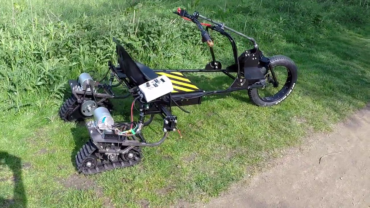
This is TrakTrike. An electriclly powered, dual track driven trike I created fpr EMF camp 2022. But it has a problem. The VSEC75100 clone electronic speed controllers I chose keep dying. I've destroyed 2 pairs since I started this project and at ~£80 each it's a bit expensive.
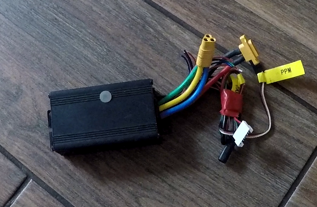
A broken VESC75100 clone
The last failure was on the first day of WHY2025. The guys from Hacky Racers were at the event and they suggested a replacement as 'anything on Aliexpress over £30'.
I took their advice and got these:
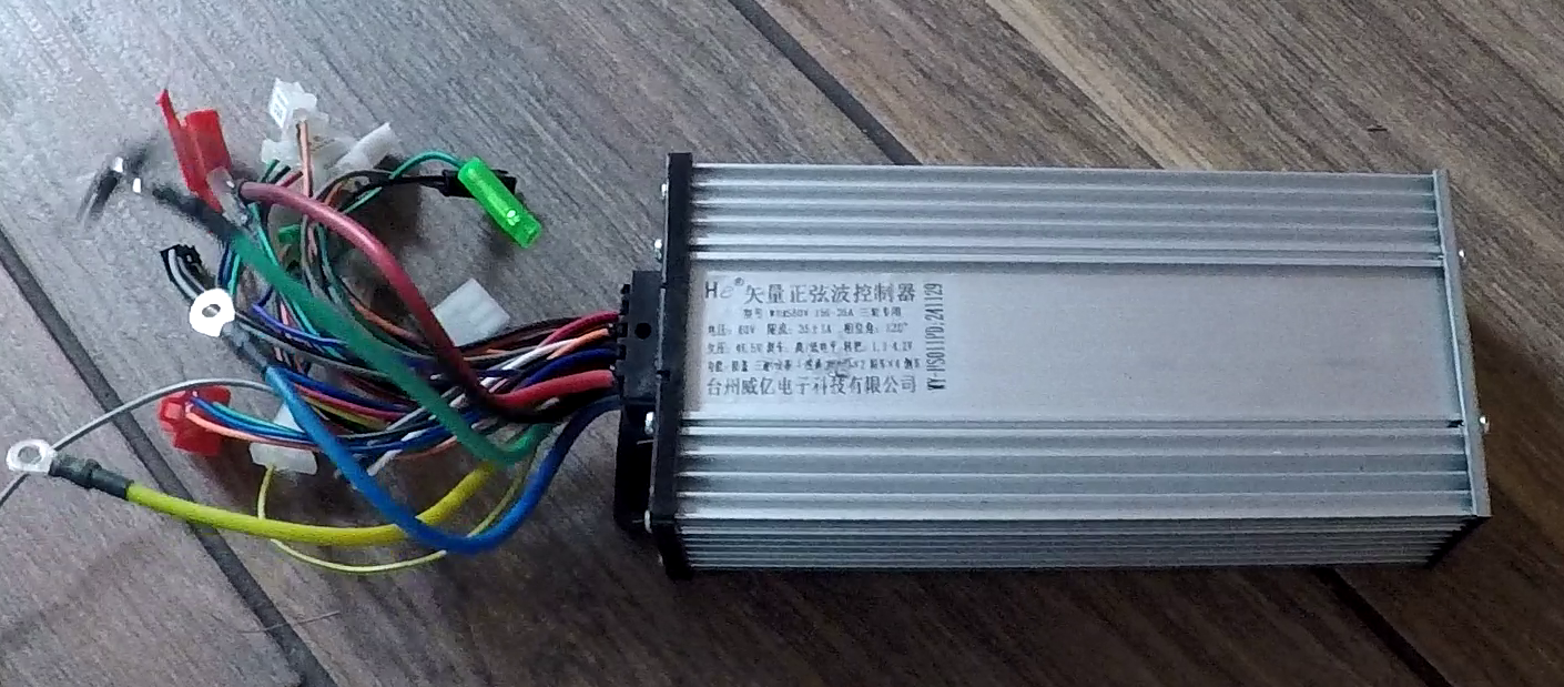
A cheap BLDC motor controller
But I discovered a couple of problems. First, the low-speed control was terrible. Small throttle movements produced no response, followed by an abrupt surge once the motors finally overcame static friction. Precise manoeuvring became difficult and sometimes unsafe.
Second, I split the throttle to connect to both controllers. Since each controller has slightly different throttle characteristics, identical throttle voltages don't produce identical motor speeds. The result is the vehicle constantly pulling to one side.
These controllers are not really designed for dual motor systems.......
So I decided to try and fix it....
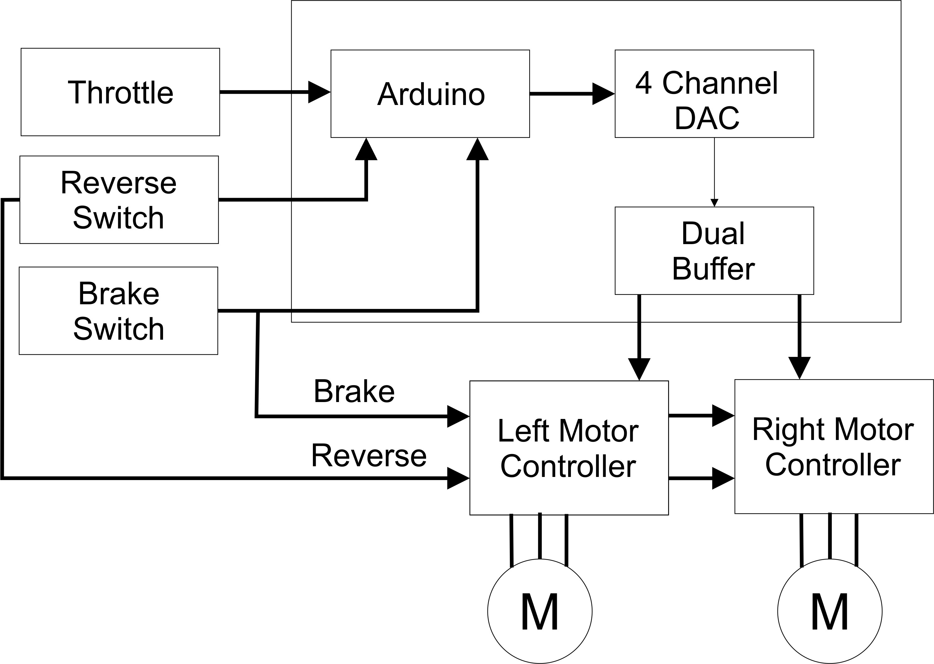
I wanted to place a throttle profiler inbetween the twist throttle and the motor controllers. I will dictate in software what the motor controller throttle inputs see!
The architecture is:
My feature list is
- Smooth, predictable low-speed control
- Eliminates jerky starts and throttle deadband
- Precise crawling speed for accurate manoeuvring
- Configurable acceleration and deceleration profiles
- Adjustable throttle response curves
- Automatic forward/reverse transition handling
- DAC output pacing to improve controller reliability during direction changes
- Individual calibration for each BLDC controller
- Supports dual rear motor controllers
- Independent configuration of left and right drive systems
- Persistent configuration stored in non-volatile memory
- Runtime configuration of important parameters without recompiling firmware
- Designed specifically for heavy, low-speed electric vehicles
- Compatible with inexpensive Chinese BLDC motor controllers
- Improves drivability without modifying the motor controllers themselves
- Built around readily available, low-cost hardware
- Open-source firmware and hardware
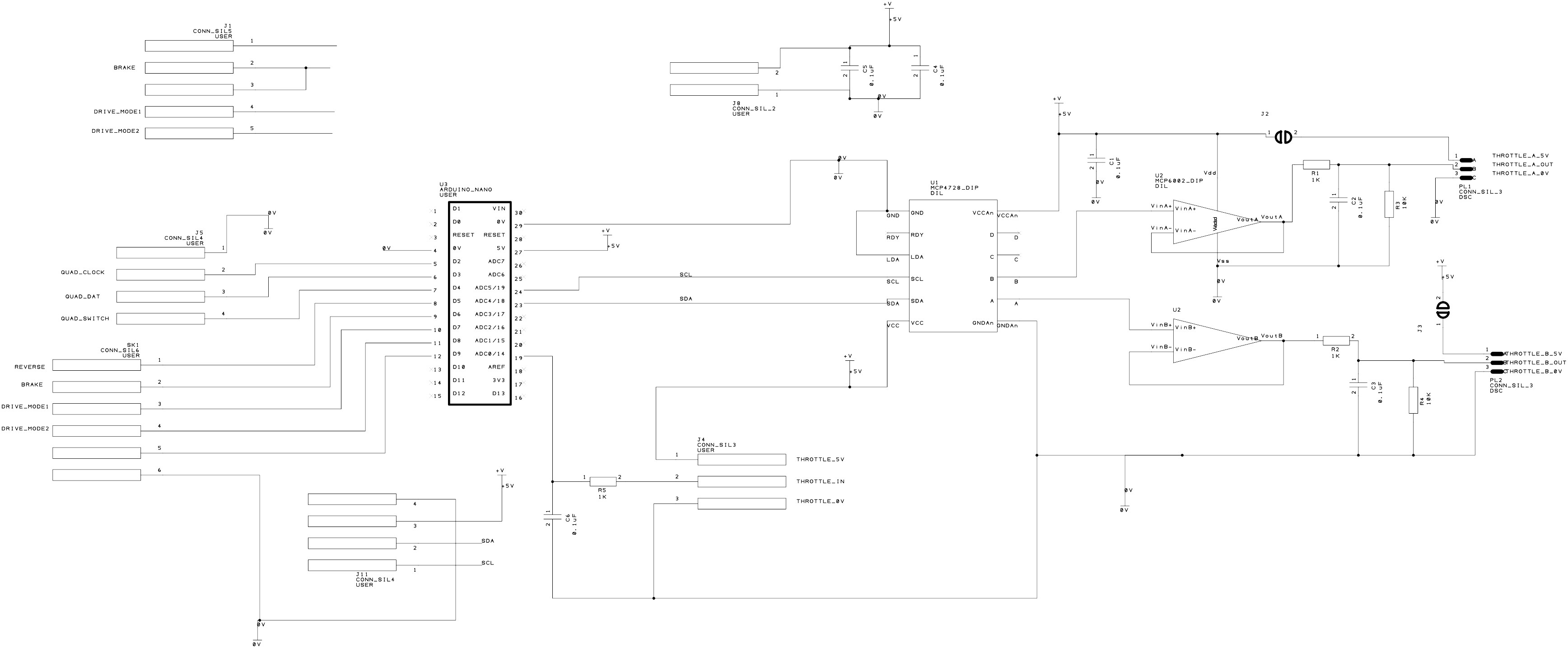
The control circuit has the following components
- Arduino Nano. There is a bit of floating point math, but nothing the nano can't handle
- A MCP4728 12 bit DAC module. This is readily available from Aliexpress and comes in a DIP package
- A MCP6002 op-amp. This works as a rail to rail voltage follower to isolate the DAC from odd input impedances of the controller.
- A I2C LCD display.
- Ports for brake and reverse switches
- A simple mode change button.
The schematic is:
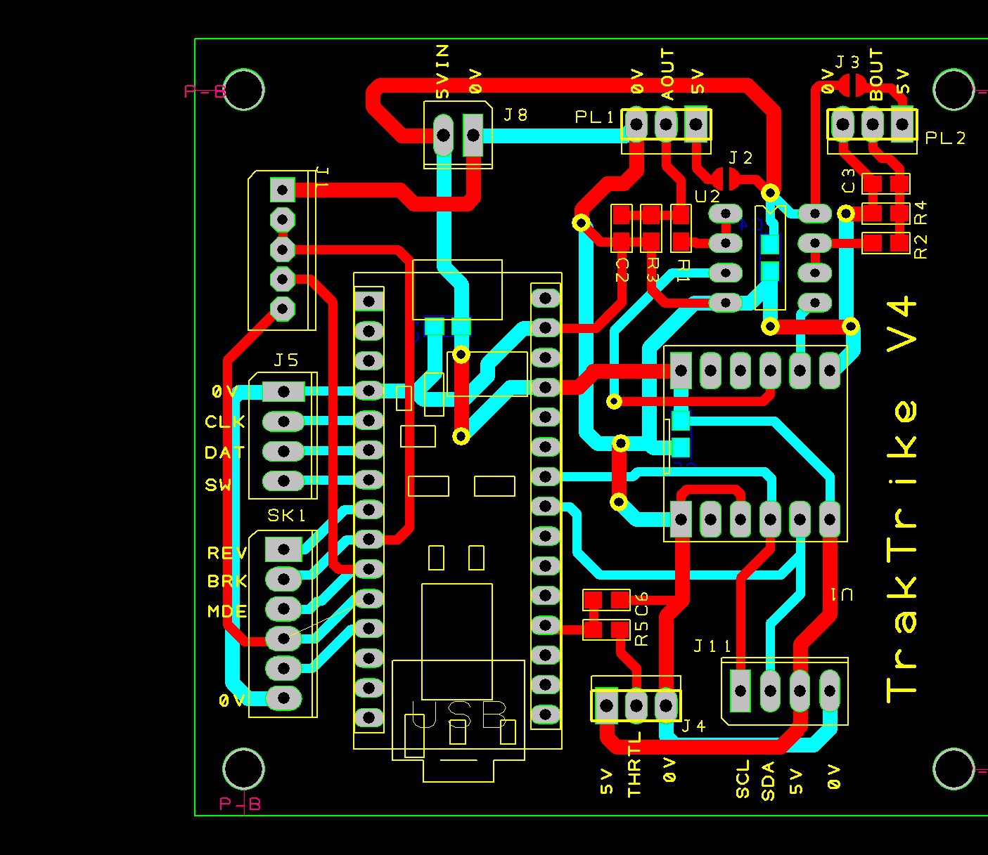
And the PCB design:
I normally CNC route my PCBs, but PCBWay kindly offered to sponsor its manufacture. The PCBs arrived within about a week of ordering and I was really pleased with the quality of the boards. The fact that the order contains 5 copies means that I can use IC sockets for the protoype and solder the ICs in for the produciton boards and have a few spares. Thanks to PCB way for sponsoring these!
If you want to get a copy oif these the files are at PCBWay.
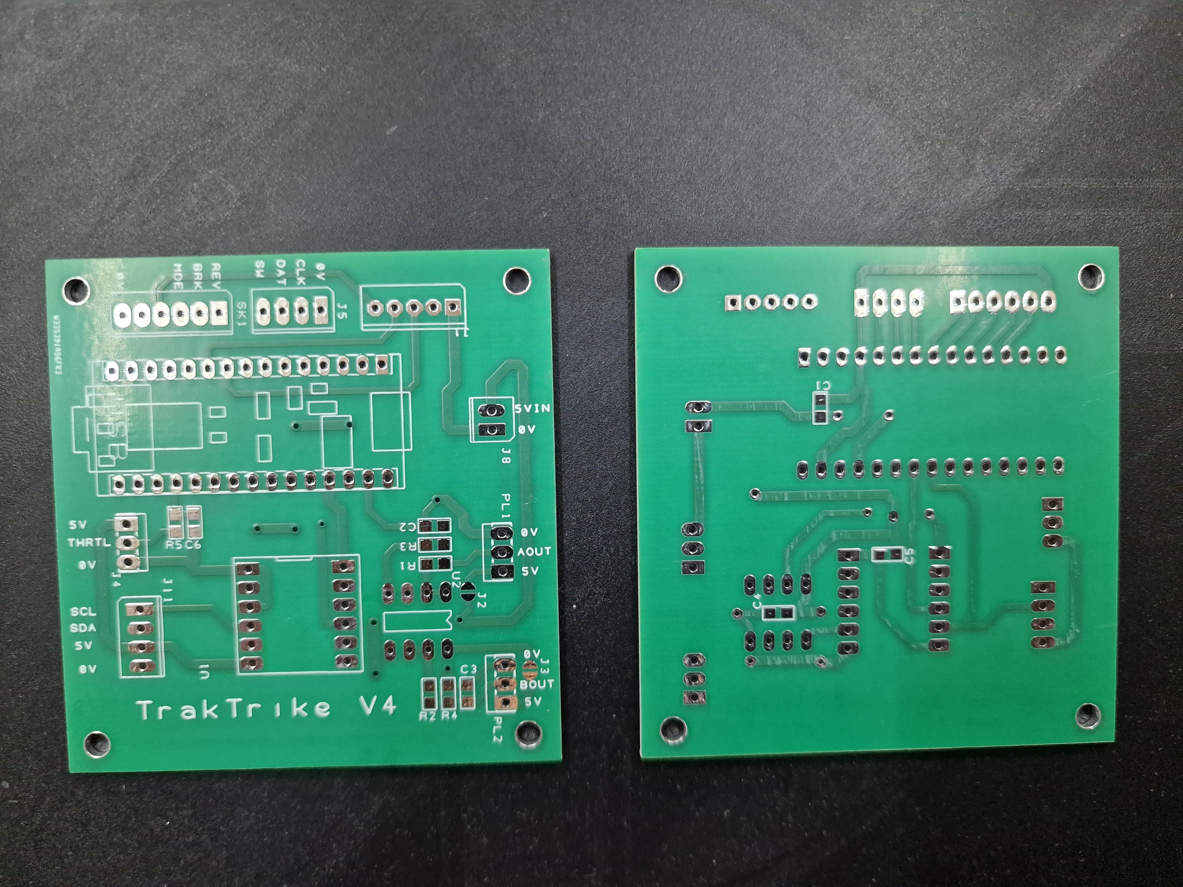
Really happy with the PCBs.
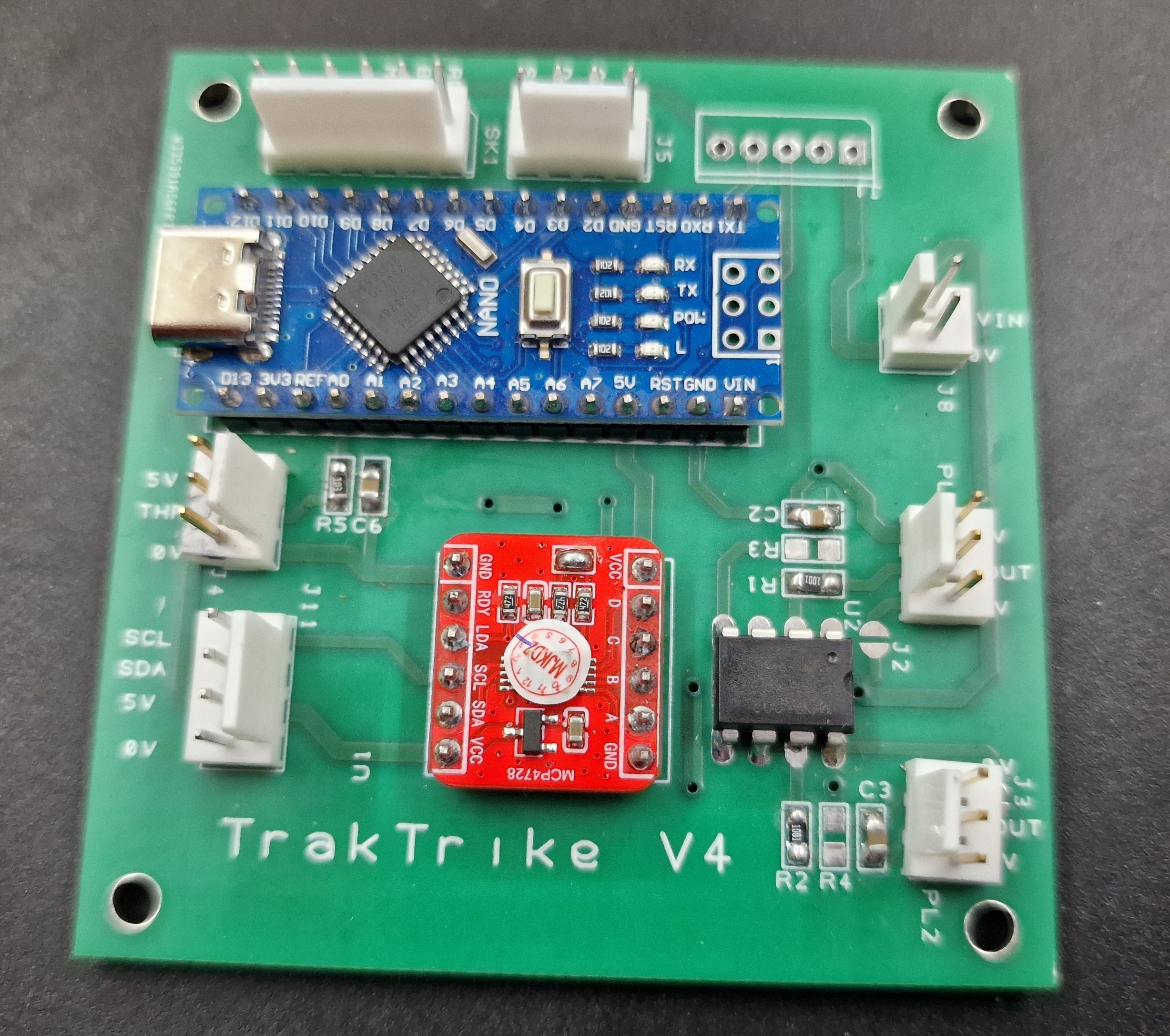
A populated production board
The software is written in C/C++ in VSCode with the PlatformIO extension. I've been developing embedded code for 35+ years and decided to try this 'vibe coding' thing the kids are talking about...and I found it very satisfying. I used ChatGPT and after describing the base function, I had a working app and while ChatGPT produced a working application surprisingly quickly, experience still mattered. I ended up pushing back on several design decisions:
- Config data stored in EEPROM and copied var by var into global variables. Just use a config struct for everything and do a memcpy.
- Config data not versioned and without checksum
- Certain config data was hard coded. I insisted it should be configurable
- I had to tell it to create add a trim function.
The trim function is essential. Using the force command I measured the rpm of each motor at points 0.1, 0.2 ...1.0 of throttle and got the following results:
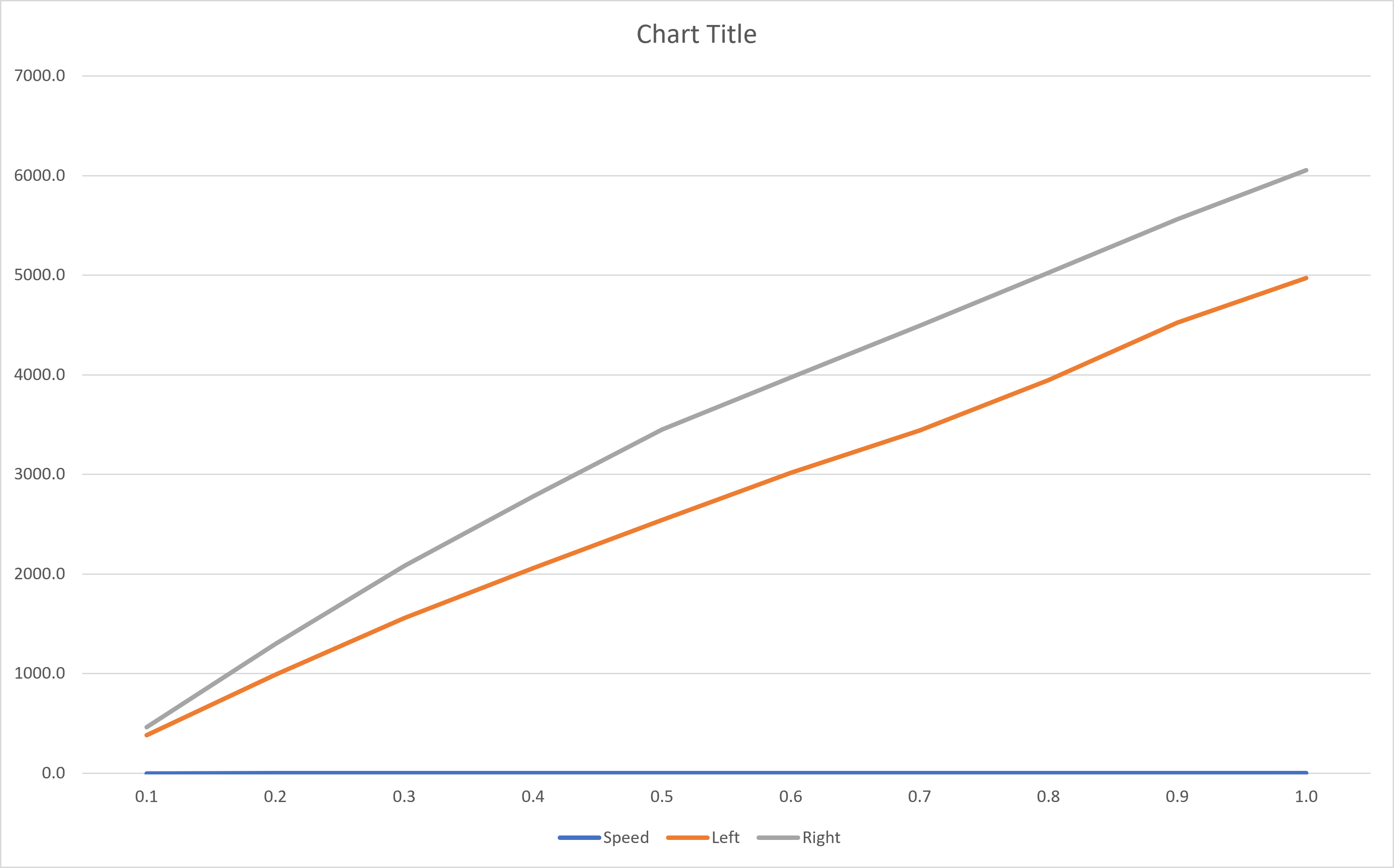
It's obvious the difference between the two controllers increases with speed. The trim calibration function takes readings for left and right speeds at a predefined throttle input and creates a trime table. These values are used to create an interpolated value at runtime.
The software is calibrated at run time by connecting the Arduino serial port to a terminal application and issuing a set of commands:
The difference exceeded my expectations. What began as a workaround for unreliable controllers evolved into a controller that makes inexpensive BLDC drives genuinely usable for precision low-speed vehicles.
Set the minimum and maximum throttle A-D values as read by the Arduino analogue port.
startl
startr
Set the minimum DAC output value that the left/right motors start to turn at.
dacmaxl
dacmaxr
Set the DAC output value at which the left/right motors are at full speed.
slowmaxl
slowmaxr
Set the maximum DAC output to be used in slow mode.
force
Forces a constant throttle output for use during trim calibration.
calibrate
Given left and right rpm, calculates a trim table entry for the current force speed.
show
showall
Displays current values
save
Save the current configuration to EEPROM
defaults
Restore hard coded defaults
The software ensures that the DAC default output values are set to zero as a safety feature. It also intialises to a 'slow mode' profile. The 'normal mode' is activated via the UI button and toggles between the two modes.
Activating the reverse swith automatically selects slow mode.
Applying the brake switch forces all outputs to zero.
When transitioning between forwards/reverse, the software forces zero outputs to the controllers and ensures the twist throttle returns to the zero position.
I found that one of the controllers failed to operate occasionally when switching between forwards/reverse, the throttle clamp above fixed this with a forced minimum throttle zero time of a few hundred ms.
After trying it in the TrakTrike the difference was amazing! Manouvering in reverse became manageable with the slow mode enabled. And the acceleration curve signficantly reduced the jerky speed increase in normal mode.
The main differences between a profiled and a stock controller are:
| Stock Controller | TrakTrike Controller |
|---|---|
| Deadband | Immediate response |
| Jerky startup | Smooth startup |
| Difficult crawling | Walking-speed control |
| Sudden torque | Progressive torque |
| Poor reversing | Controlled transitions |
This project doesn't attempt to replace sophisticated field-oriented motor controllers. Instead, it extends the usefulness of inexpensive commodity BLDC controllers, making them suitable for low-speed electric utility vehicles, robots, dual motor drive platforms and other projects where smooth, predictable control is more important than outright performance.
I'm really please with how this turned out. I'm contemplating a MK2 with the addition of reverse mode outputs to the BLDC controller reverse lines. In my dual drive system I've had to change the phase wiring on one side to reverse the motor direction. Having this controlled in software would enable me to add a reverse left/right configuration.
Discussions
Become a Hackaday.io Member
Create an account to leave a comment. Already have an account? Log In.