 aintmina
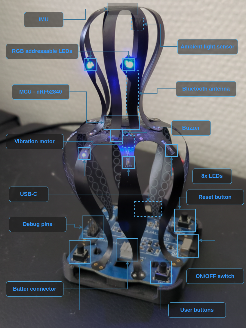
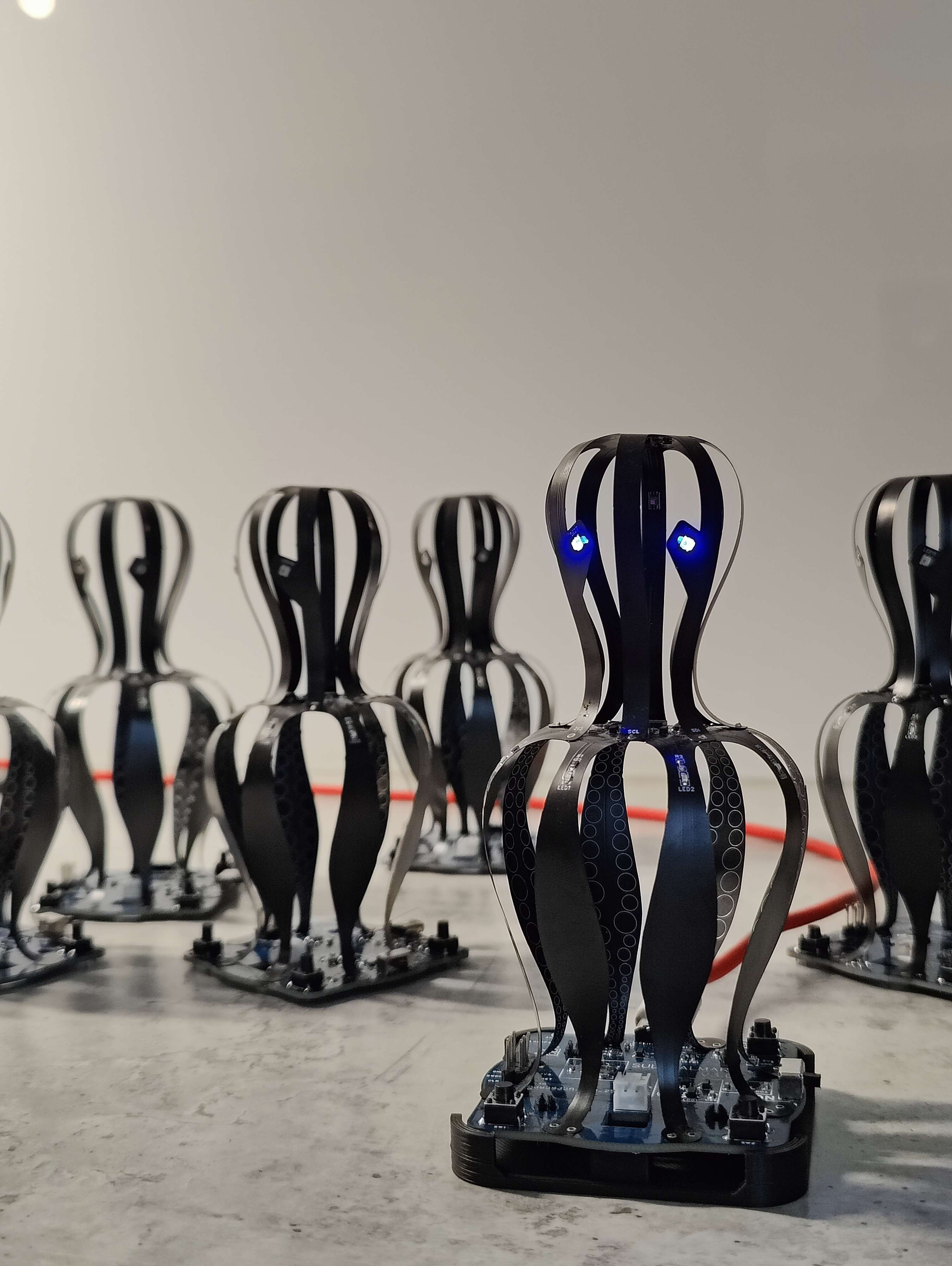
What is this wobbly device?
At first glance, you might think we built an elaborate paperweight, but it's probably not even heavy enough for that. This is me and my friends first take on designing an MCU PCB, and of course we had to overengineer it and make it as complicated as possible. But where's the fun of making things easy.
This device was not created to serve a purpose, but to teach us PCB design and project work. It ended up as a flashy desk toy which wobbles on slightest movement, but also gains attention by confusing people around it.
Story
The story started when laying on sofa, staring at the ceiling, I got the idea of creating a flex-PCB and have it be 3-dimentional. The shape was easy, since I worked in a company called Qalmari and their mascot is an octopus which was perfect for this project (also perfect for getting the company to pay for this expensive project :D).
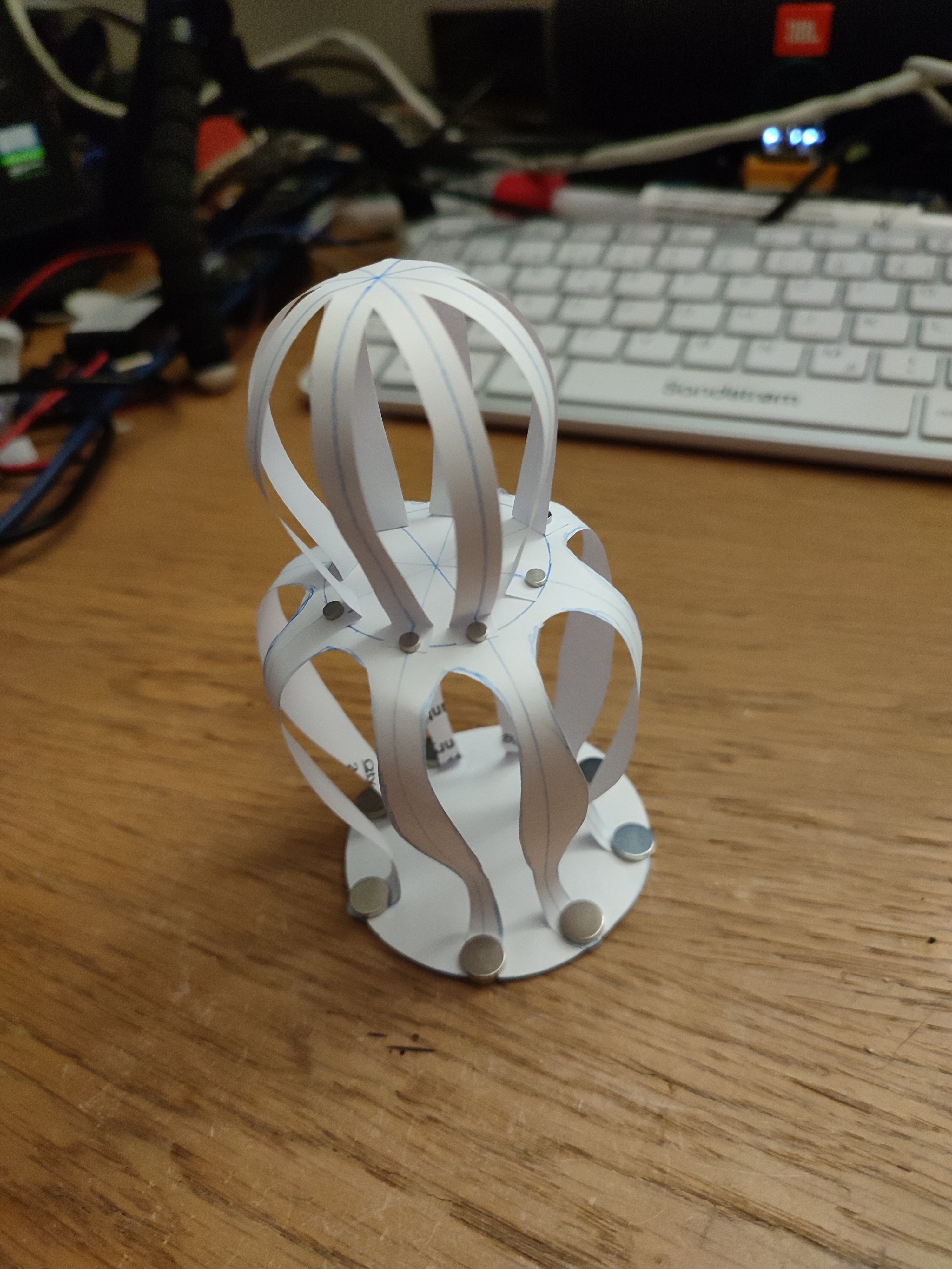
First step was to create a paper cutout and message my friend if he wants to collaborate on this project. I grabbed some cheap whiskey, we got components for whiskey sour (first time making it), and started designing the project.
We wanted to have bluetooth on it, but our school project with nRF chip was a disaster and we started to hate it and zephyr. But still, we decided to give it another chance and use the nRF52840 as the MCU.
I love creating weird and useless projects and I'm extremely proud of this one. This taught us so much, we got a cool project for our portfolio/CV, and we got an actual device on our desk as a reminder for this.
Prototype 1
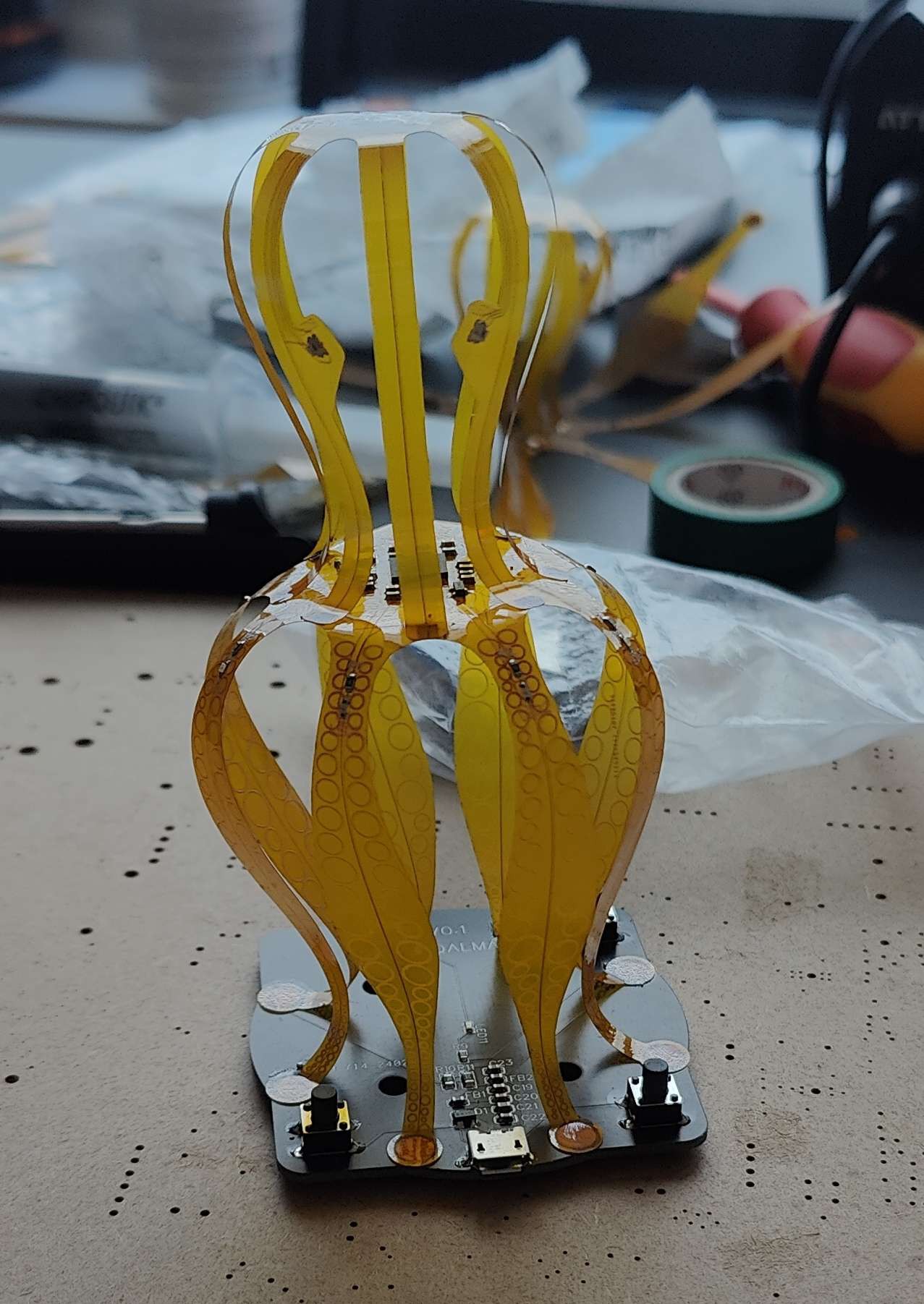
The first prototype was designed while learning to make whiskey sour, and the result was not that good (who would've guessed). We had so many DRC errors, since we didn't set any design rules and the tolerances were too small for them, we missed a critical flaw of an accidental via from 3V3 straight to GND.
When receiving the prototype, we didn't know this and didn't have tools to find it, so we just pumped some current through and found that one leg had the whole track turning black. But this prototype proved that the mechanical concept was legit.
Prototype 2
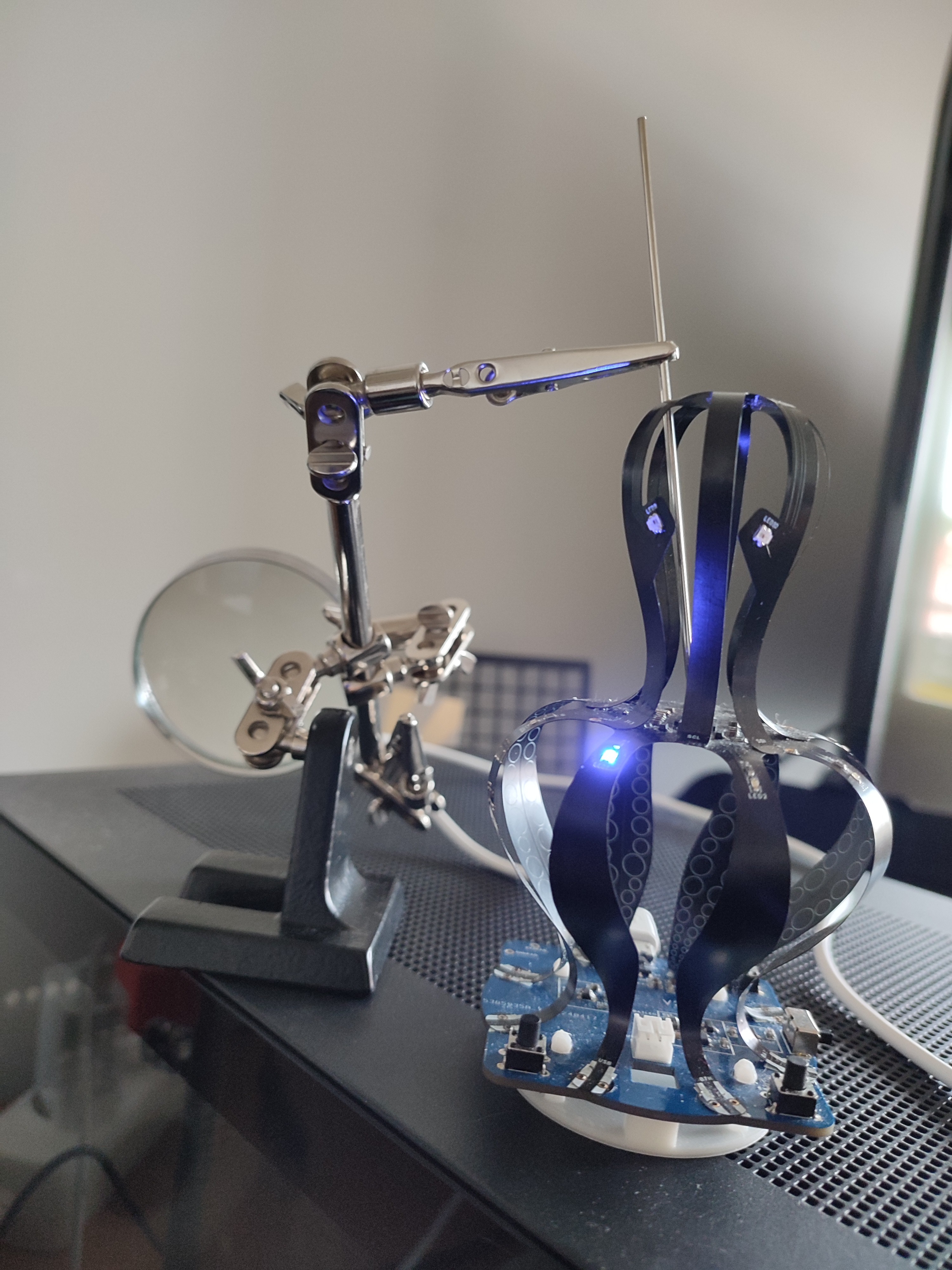
For the second version, we switched from yellow to black/blue, to contrast the company colors and it looked way better than the first prototype. This time, we followed and solved all the DRC errors and got the device to work. This was also the version which allowed us to test our minimal bluetooth antenna, and it worked (don't ask about the efficiency)!
But this one was NOT without problems. Turns out, clamping to debug pins on the flex-PCB was eventually fatal to the pins and we lost access to debugging on many of the devices. We also did a lot of stress testing by smashing the device flat, to see if it can take it, and it did... for a while. After stressing it for a while, we found that some pins from the MCU got disconnected from the PCB and the device did not work properly without pushing on the chip.
Prototype 3
After breaking all the second stage prototypes, we decided to do final batch as "ready" devices. This fixed the debug pins and added a stiffener on the other side of the MCU to protect the pins. We also noticed that the vibration motor did not function as we wanted, so we didn't assemble it on the final device.
Hardware
If you're crazy enough to want to get your own expensive useless device, then the hardware files are freely available at my git as gerbers and diagrams. This was designed in EasyEDA for the convenience of not having to build our own component library, but this has made releasing the CAD project difficult...
* CPU: nRF52840-QIAA MCU (on a flex PCB).
* Sensors: ICM-20602 IMU and XYC-ALS21C-K1 I2C Ambient Light Sensor, bluetooth PCB antenna.
* Fun stuff: 2x WS2812B RGB LEDs (the eyes), 8x blue indicator LEDs, Buzzer/Vibration Motor mounts, 2x user buttons.
* Power: TP4054 battery charger, two separate LDOs (3V3 and 3.6V).
* Structure: Two custom flex PCBs (Head & Legs)...
 Taiwo
Taiwo
 Christian
 Crypto [Neo]
 sjm4306