 Sciter
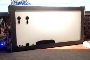
This project is a custom VFD clock built from a recycled calculator vacuum fluorescent display.
The display is driven by an ATmega328P microcontroller and an HV5812 high-voltage shift-register driver. The clock uses multiplexed VFD driving, controlled blanking, automatic brightness control, USB power detection, battery voltage monitoring, RGB ambient lighting and status diagnostics.
One of the main goals was to make the clock operate from a single AA NiMH cell, rather than from a lithium cell or a conventional multi-voltage supply. USB 5 V can be connected for normal operation, while the NiMH cell remains part of the power system. The design includes Schottky OR-ing of the 5 V branches, a local VFD oscillator inhibit function, and additional capacitance on the 5 V logic rail to prevent brownout during power-path transitions.
The VFD power section was one of the most challenging parts of the build. The project required testing the original-style filament and high-voltage converter, solving VFD ghosting issues, tuning the multiplex timing, and adding safe firmware control for blanking and oscillator shutdown.
Later revisions added diagnostic LEDs for 5 V, USB, VFD high voltage and filament activity. The HV and filament indicators are sensed by the ATmega through high-value resistor dividers, so the sensitive VFD power supply is not significantly loaded.
The final clock combines reused vintage display technology with a compact custom control system and a cyberpunk-inspired mechanical design.
 Vadim Teselkin
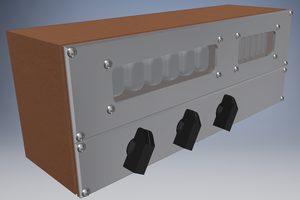
 Charles Ahrens
 Jung Hoon Lee
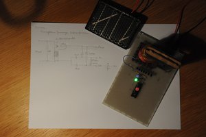
 Matthias Koch