 Yann Guidon / YGDES
The real circuit uses pairs of A21OI gates to create a latch.
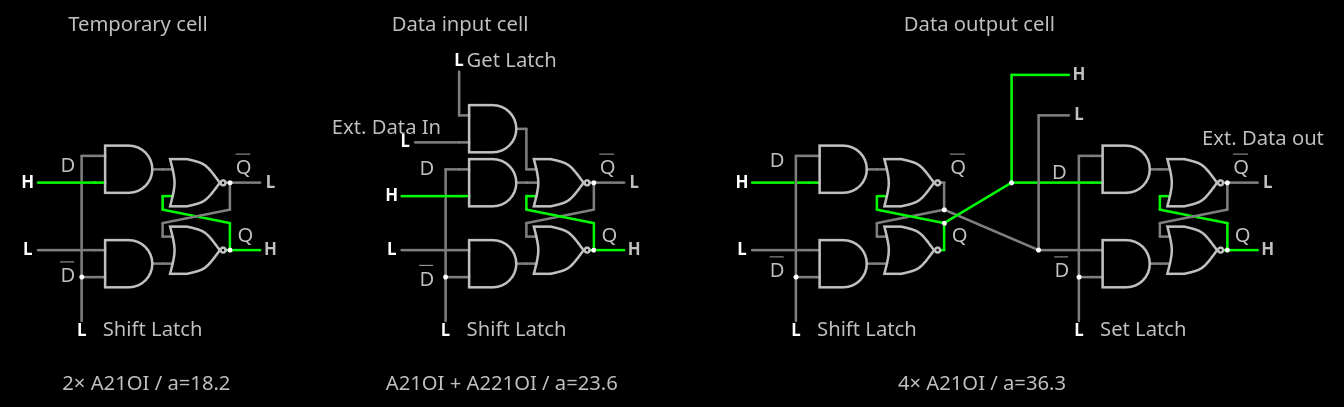
Due to routing considerations (keeping the inter-latch wires on M2 but preventing crossings), the Q outputs actually go to /D and vice versa. It can create quite a confusion but since the latches come in pairs, the polarity is restored at every bit. It's easy to get confused though, particularly with the inter-macro connections.
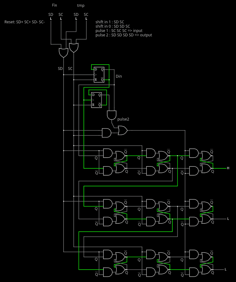 (don't mind the mislabeled inputs)
- So inside the pseudo-FF, the /Q output (controlled by SD) goes to the next Q input and vice versa.
- Outside, the /Q output of the SC slice goes to the Q inputs of the output buffer (controlled by Pulse2/Update) and the Q input of the next SD latch.
- In the layout, Q(SC) is tied to D(update), so the actual output is taken from /Q(update)
.
Discussions
Become a Hackaday.io Member
Create an account to leave a comment. Already have an account? Log In.