Michael Wessel
Philips MC6400 Vector Graphics
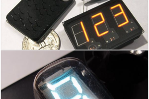
Real-time 3-D wireframe vector graphics — a rotating cube, torus, and sphere — drawn on an analog X-Y oscilloscope, computed live in INS8070 machine code on a 1984 Philips MC6400 "MasterLab" CPU trainer.
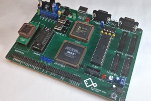
The MasterLab has a 1 MHz National INS8070 (SC/MP III) CPU and 1 KB of RAM. With a small home-made R-2R DAC on its expansion bus — plus one tiny analog trick (an RC slew-limit, see below) — it drives a scope in X-Y mode and tumbles solid wireframe solids in real time, all in well under a kilobyte of code.
Programs are loaded onto the machine with PicoRAM Ultimate — a Raspberry Pi Pico-based (S)RAM/ROM emulator and SD-card interface for vintage single-board computers. As far as I know this is the first expansion-port peripheral ever built for the MasterLab.

The full rig: a Philips MC6400 with the home-made R-2R DAC on its expansion bus (right), driving a Tektronix 2335 analog oscilloscope in X-Y mode (left) — drawing a solid, rotating 3-D cube. Everything runs live in under 1 KB.
How this was made. Every line of code, all of the tooling (the INS8070 assembler, cycle-accurate simulator, and oscilloscope renderer), all of the assembly programs, and the R-2R DAC hardware design in this repository were written by Claude (Anthropic, Opus 4.8) working under my direction, from the assembler all the way to the rotating sphere and the on-hardware bring-up. I (Michael Wessel) supplied the hardware, the MC6400 manual and INS8070 references, the goals and design choices, and — crucially for this project — the testing and feedback on the real scope at every step.
Status: built and running on real hardware ✅
The R-2R DAC is built and verified on a real Philips MC6400, driving a Tektronix 2335 analog oscilloscope. It draws solid, continuously-rotating 3-D vector wireframes — cube, torus, and sphere — live, in under 1 KB of INS8070 machine code each. The photos below are the real scope, not renders.


Cube, torus, and sphere — solid analog vectors on a Tektronix 2335, computed and streamed live by the MC6400.
The one surprise: you need an RC slew-limit
Getting from "it runs" to "you can see vectors" turned out to be the whole story of the hardware bring-up, and it's worth documenting because it is not obvious and it bites everyone the first time.
The problem — dots, not lines. The DAC is a step DAC. Writing a new (X, Y) makes the op-amp jump to the new voltage in a few microseconds; the CPU then parks there ~100–200 µs while it computes the next point. So the beam spends almost all of its time sitting on the vertices (bright dots) and only microseconds sliding between them (near-invisible). Out of the box you get a recognisable but dotted figure — never solid lines — no matter how you set up the scope. Cranking the intensity just blooms the dots.
Why the scope's own "vectors" don't save you. An analog scope has no "vector mode" — its beam is always drawing wherever X,Y are; the issue is purely that it flies between points too fast to light them. A digital storage scope does have a "Display Vectors" option, but in X-Y it connects consecutive samples in acquisition order, sampled asynchronously to the DAC with a bandwidth-limited horizontal channel — so DSOs are simply poor X-Y vector monitors (see Scopes). We chased this for a while before realising it's fundamental.
The fix — draw the lines in hardware. Real vector displays (Vectrex, Asteroids, Tektronix storage tubes) move the beam at a constant velocity between endpoints so the whole line lights evenly. You can approximate that on this DAC with a two-part, reversible add-on: slew-limit each output with an RC low-pass, so every DAC step becomes a ramp. The beam then sweeps continuously along each edge — the dots...
Read more »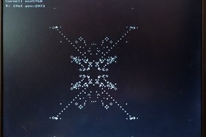
 Bruce Land
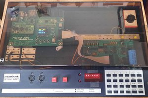
 Colin Maykish