 nobcha
In the previous log, I talked about why this project exists. Now, let's get into the what – the hardware.
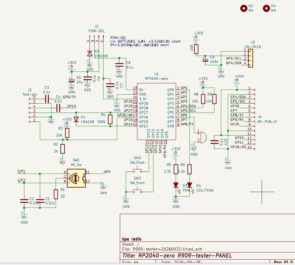
The core of this instrument is the Raspberry Pi Pico Zero (RP2040) of Waveshare. It's cheap, powerful, and has enough I/O to handle all the functions I wanted to pack into this tester.
Here’s a quick tour of the main hardware blocks.
The Brain: Waveshare RP2040 Zero
I chose the Pico Zero because it gives me a complete, ready-to-use RP2040 board in a compact form factor. It already has the large flash memory, and the USB port, so I can focus on the application circuitry. The dual-core Cortex-M0+ and the PIO (Programmable I/O) are also big pluses – especially for the frequency counter, which I'll talk about in a later log. Comparing with ATmega328P it's attractive for USB-IF and large memory.
User Interface: OLED + Rotary Encoder
For display, I'm using a small SSD1306 OLED (I2C interface). It's simple, low-cost, and perfect for showing measurements and menus. The rotary encoder (with a built-in push switch) handles all user input: turn to select functions, press to confirm. No touchscreen, no complex keypad – just a clean, minimal interface.
Continuity Tester:
This uses a simple voltage divider on an ADC pin (GPIO26). The firmware reads the voltage and decides if the circuit is open or shorted. V-open and I-short is enough small to avoid bad influence for the circuit on testing. I
There's also a buzzer (on GPIO6) that gives audible feedback – because sometimes you just want to listen for the beep.
Capacitance Meter:
This is based on the classic RC charge time method. A known resistor (100kΩ) charges the capacitor through a test terminal, and the firmware measures the time for the voltage to reach 63.2% of the supply voltage (VCC) on an ADC pin (GPIO26). From that time (τ = RC), it calculates the capacitance. There’s a small trick to discharge the capacitor quickly between measurements using a GPIO pin as a switch. At first I let GPIO26 change as a digital port, but in vail GPIO26 will not work so.
Frequency Counter:
This one uses the RP2040's PIO feature. The PIO can count pulses very fast and accurately without bogging down the CPU cores.
Diode Identifier:
This function measures the forward voltage drop (Vf) of a diode using a constant current source.
Power and PCB
The whole circuit is currently running on a breadboard. That's how I test and iterate quickly. I'm currently working on a custom PCB to make it more robust and portable, and I'm in talks with a PCB manufacturer to get the board made.
Discussions
Become a Hackaday.io Member
Create an account to leave a comment. Already have an account? Log In.