 nobcha
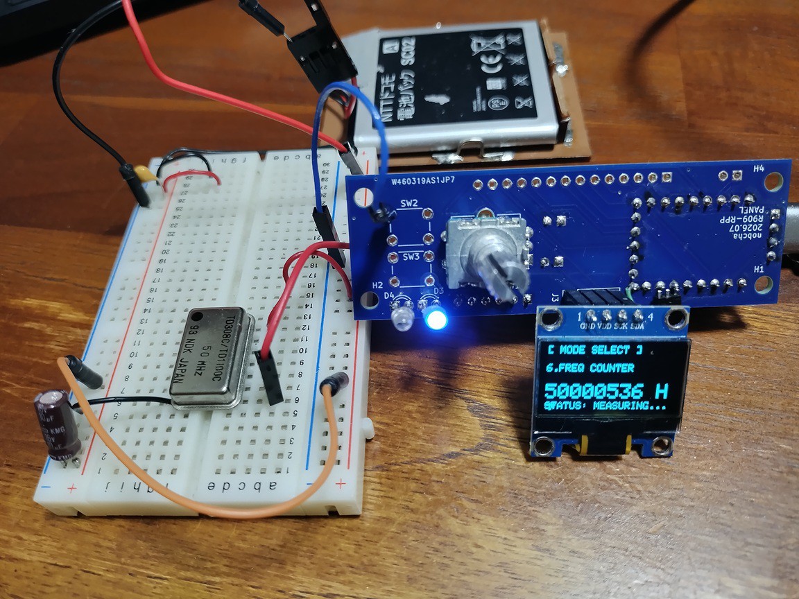
To speed up my experiments and add more features, I decided to design and build a custom PCB. However, during PCB layout, I accidentally flipped the orientation of the I2C pin header for the OLED display and routed it on the wrong side! Fortunately, it doesn't affect debugging at all—I just mounted the display turned around, and it works fine for now.
https://nobcha23.hatenablog.com/entry/2026/07/20/191050
The tester includes a continuity tester, capacitance meter, diode checker, and a frequency counter. Surprisingly, the frequency counter responds up to 50 MHz!
---50MHz displaying
I've uploaded the Gerber files for this PCB to GitHub.
--Link address Gerber sketch:
https://github.com/Nobcha/R909-tester/blob/main/R909-tester_Rev1.0_ERRATA.zip
Discussions
Become a Hackaday.io Member
Create an account to leave a comment. Already have an account? Log In.