- SESSION #1 (2/17) : First, after watching some links and videos about DIY-Dynamo charger projects, we have listed all the components needed for our project.
- SESSIONS #2 (2/24) & #3 (3/03): After ordering all the stuff (shopping list in the description), we have designed and modelized the gears for the motor which will be 3D-printed thanks to the software AutoDesk Fusion 360 (Fig 2). Moreover, we have recieved our first component: an ordinary dynamo lamp. We have opened it and studied its components, how the gears work, etc. We have taken the motor in order to use it later (Fig 1).
![]() Fig. 1: Inside a dynamo lamp
Fig. 1: Inside a dynamo lamp![]() Fig 2: One of the gears modelizing by Max
Fig 2: One of the gears modelizing by Max - SESSIONS #4 (3/10), #5 (3/24), #6 (3/31): Once we recieve all the main components, we started realizing the electronical part of our dynamo charger. We tested several electric circuits by adding or removing some components to study their impact on the power of the dynamo (Fig 3). By doing this, we observed which components maximaze the electric power in our lamp. We have also printed our first 3D-printed gear. (Fig 4)
![]() Fig 3: Realizing the electrical circuit of our dynamo
Fig 3: Realizing the electrical circuit of our dynamo![]() Fig 4: Our first 3D-printed gear
Fig 4: Our first 3D-printed gear - SESSION #7 (4/21): We started assembling the 3D-printed gears. We had some issues with the rotation (not very smooth). After 2 or 3 complete turns, the gears stopped rotating. It is probably because of the shape of the gears which doesn't allowed a smooth rotation. We tried several montages. + Voltage
![]() Fig 5: Assembling the gears
Fig 5: Assembling the gears - SESSIONS #8 (4/28) & #9 (5/05): In order to solve the problem and to advance in our project, we eventually take the original gears in the dynamo lamp. After testing our electrical circuit, we had some issues with the device when recharging it. The power given to the phone is not enough. But we continue fixing problems. Moreover, the balance between the power supply and the voltage is hard to reach. Indeed, after a successful test with a LED, we did the same with a cell-phone : the tension measured thanks to the multimeter enough unlike the current... In the same time, we started the creation of the box. We imagined the optimal dimensions for the box: we cut some wood and assembling the box thanks to the glue. It was hard at the begining because the material was too smooth but at the end, we use the glue gun. It was more efficient.
- SESSION #10 (5/12): To solve this problem, we removed the resistor in the montage: Thus, the current is supposed to be higher. It was the case but this time, the voltage was too low and we could charge the phone with a limited time. (it doesn't work very well...). We have even made some tests with an oscilloscope.
- SESSIONS #11 (5/19) & #12 (additional) (5/29): The project wasn't finished but we tried to finalise the design at least.
Dynamo Kit for Cellphones
We want to stop the waste of energy made by cellphones by recharging it with a dynamo kit.
 asquare2m
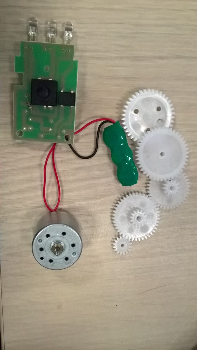 Fig. 1: Inside a dynamo lamp
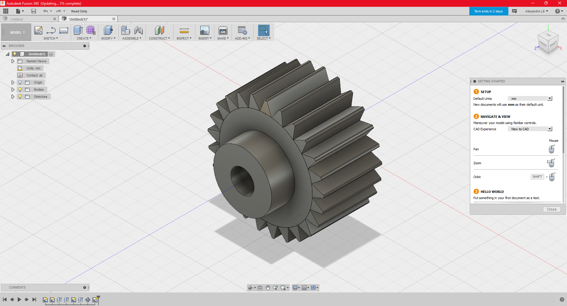
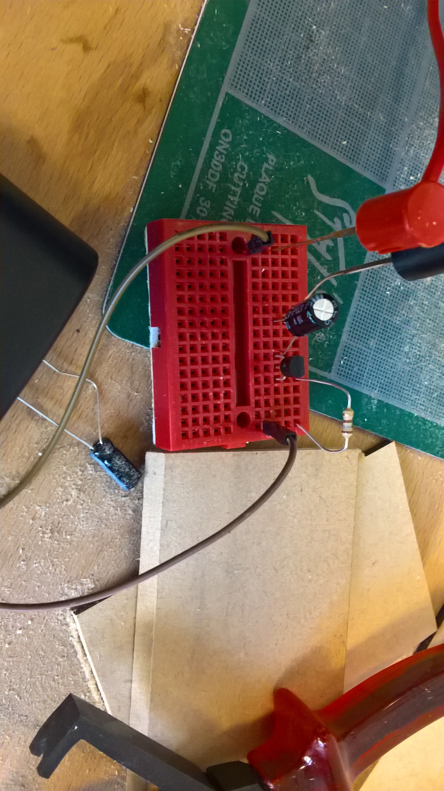 Fig 3: Realizing the electrical circuit of our dynamo
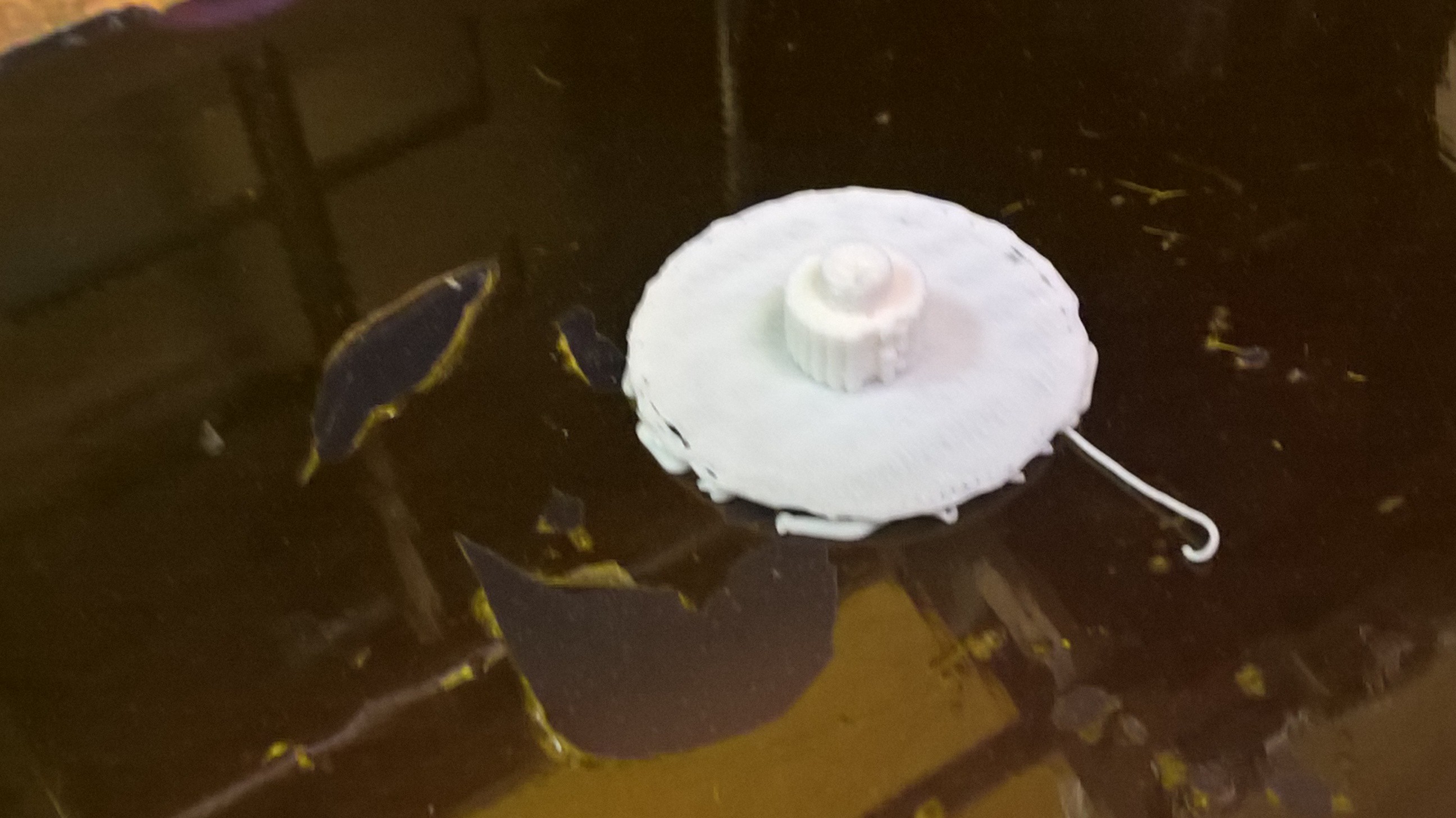
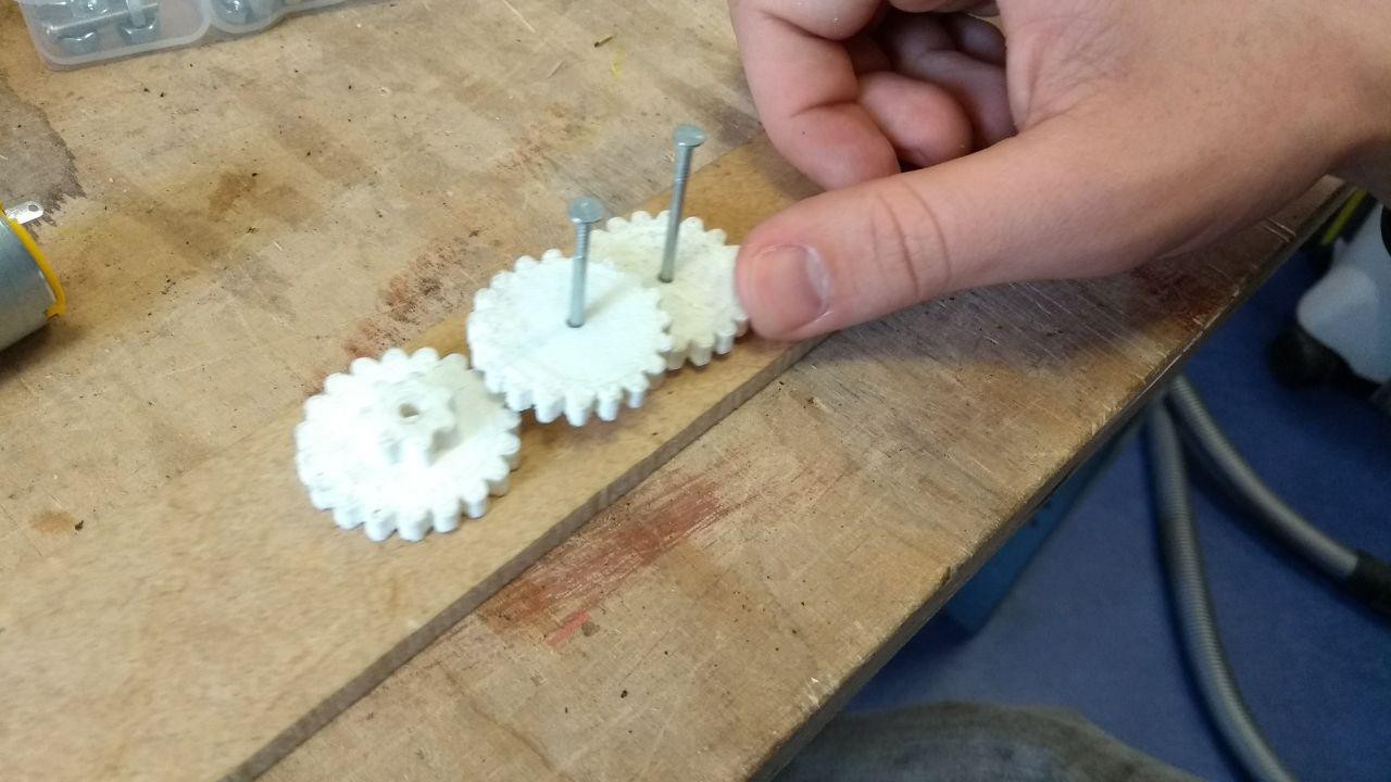 Fig 5: Assembling the gears
 alnwlsn
 Josh Starnes
 AccidentalRebel

 tobychui