Close
0%
0%

Retro-fitting USB-FIFO modules

Wiring them to existing RAM or UART sockets

Similar projects worth following
0 followers
The key idea here is to fit modern USB FIFO modules on machines that don't have a socket for one, by using existing UART or static RAM sockets.

Most PCs abandoned RS-232 by 2004. They are "not recommended for new designs" unless you have a good reason for one.

Existing vintage or hobby computer designs that have a serial port usually have a UART that is 115.2 kbaud at best.

Retro fitting a USB interface allows a PC terminal program to cut and paste large amounts of text. E.g. entire BASIC program listings. Or be used for transferring files without the need for memory cards or disk drives.

This project discusses how to kludge high-speed USB comms onto existing machines.

Many old machines and modern hobby projects have UART chips that have many disadvantages.

  • Usually obsolete 
  • Expensive or Hard to get
  • Small or non-existent FIFO buffers, causing missing characters from modern PCs
  • Need RS232 buffers
  • Need RS232-to-USB dongles to talk to modern (post 2004) PCs
  • Need +/-12V power rails (unless the buffers generate these rails)
  • Often need baud rate generators and crystals
  • Over 520 times slower than USB 2.0 (115.2 kbaud vs. 60 megabits/s)

So there is strong motivation to replace them with a USB FIFO interface.

This can happen in new designs, e.g. https://hackaday.io/project/202193-beanzee

Upgrading boards with UARTs could be done by having the USB device sit in the UART socket.

  • Pro: The USB chip select signal is on the socket
  • Con: Needs different pinning for each type of UART

I had the idea of taking most of the signals from a static RAM socket. These are always in the same place, as per the JEDEC standard, unless the board has swapped address and data lines around (unlikely). The downside is:

  • Pro: Suits any board with a static RAM socket (even boards without UARTs!)
  • Con: The USB chip select signal will have to come from a flying wire

Next problem is the handshaking flag bit positions. These differ between UART chips. The options are:

  • Software: Modify the firmware to use the flag bits where the USB module status has them
  • Hardware: Route the status pins to where the existing software expects them

My preference is for the hardware solution. The right choice will depend on the situation.

The ideal situation is if the flags are in the right place already. This is the case for the 6850 UART, which is known to drop characters from the PC due to having no FIFO and the FTDI chip sending up to four characters after being told to stop. So that is a prime candidate for replacement.

Other points to note:

  • All the UARTs I investigated have flags that go active high when the receiver has data to read and when the transmitter is ready to send data. 
  • The FTDI modules have these flags driving pins active low, and need inverting when read.
  • Using an SRAM socket

    Keith2 days ago 0 comments

    This proposed example assumes there is an available 24-pin 2K SRAM socket.

    You will need a module that supports USB FIFO mode.

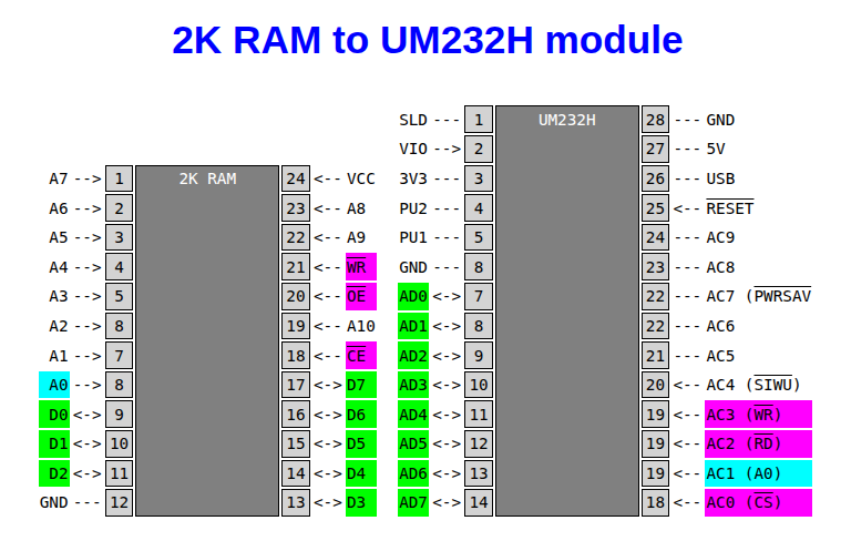
    The figure below shows the position of the signals in an SRAM and an FTDI UM245H module.

    An old module, it has a mini-USB connector which was quickly replaced by the micro USB and then the USB-C connector. If you buy a modern module, I'd recommend getting a USB-C type which is the most common type in use in 2026. It will probably have a different module pinout, but the principle is the same.

    Most of the signals are an easy join-the-dots exercise. The ground, and data bus.

    Don't connect your 5V rail with the USB 5V rail, unless you are using the USB to power your board.

    The usual case will be to piggyback onto an existing RAM. You do not use the RAM chip select, unless you are replacing the RAM chip with a USB module.

    The read and write signals may be used, but with caution. The USB module I plan to use expects separate strobes like the Z80 uses. The original board might have a 6502 or 6809, which has a read-not-write signal and a phase-2 or E signal. 

    The AC1 pin selects the data in/out or the control/status register. Using A0 is the usual address line, allowing the module to occupy two adjacent bytes. You could use any other address line, if you have  a good reason. 

    Example 1: Ciarcia's Z8001 Trump Card

    The first board that I want to upgrade is a modern remake of Steve Ciarcia's Z8001 board. This has no UART at all, and communicates through a 2K SRAM, dual-ported  to an 8-bit ISA bus. There are counters to turn it into a FIFO buffer. I have no ISA bus, so it would be much better to communicate through USB.

    The USB-FIFO module has its own internal FIFO, so the external counters driving  RAM address lines become redundant. A0 will still toggle between data and status for every odd/even address, which is not wanted. AC1 will thus have to be driven by an address line that differ between the SRAM select and the status register. One way might be to have AC1 connected to the RAM /CE signal. If the 2K RAM is being accessed, it is trying to select FIFO data. If the RAM is not accessed, it is not addressing  FIFO data, and thus the USB module presents its status byte.

    AC0 needs to be active when the board is selecting the 2K RAM socket (the original RAM being removed), or the status byte address.

    The board is still being debugged by the designer, so I am waiting until that is completed.

View project log

Enjoy this project?

Share

Discussions

Similar Projects

Does this project spark your interest?

Become a member to follow this project and never miss any updates