Arnov Sharma

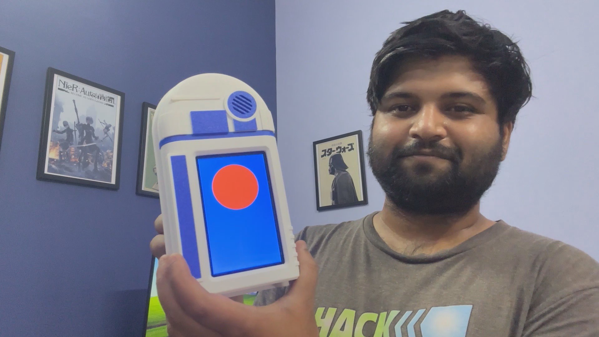
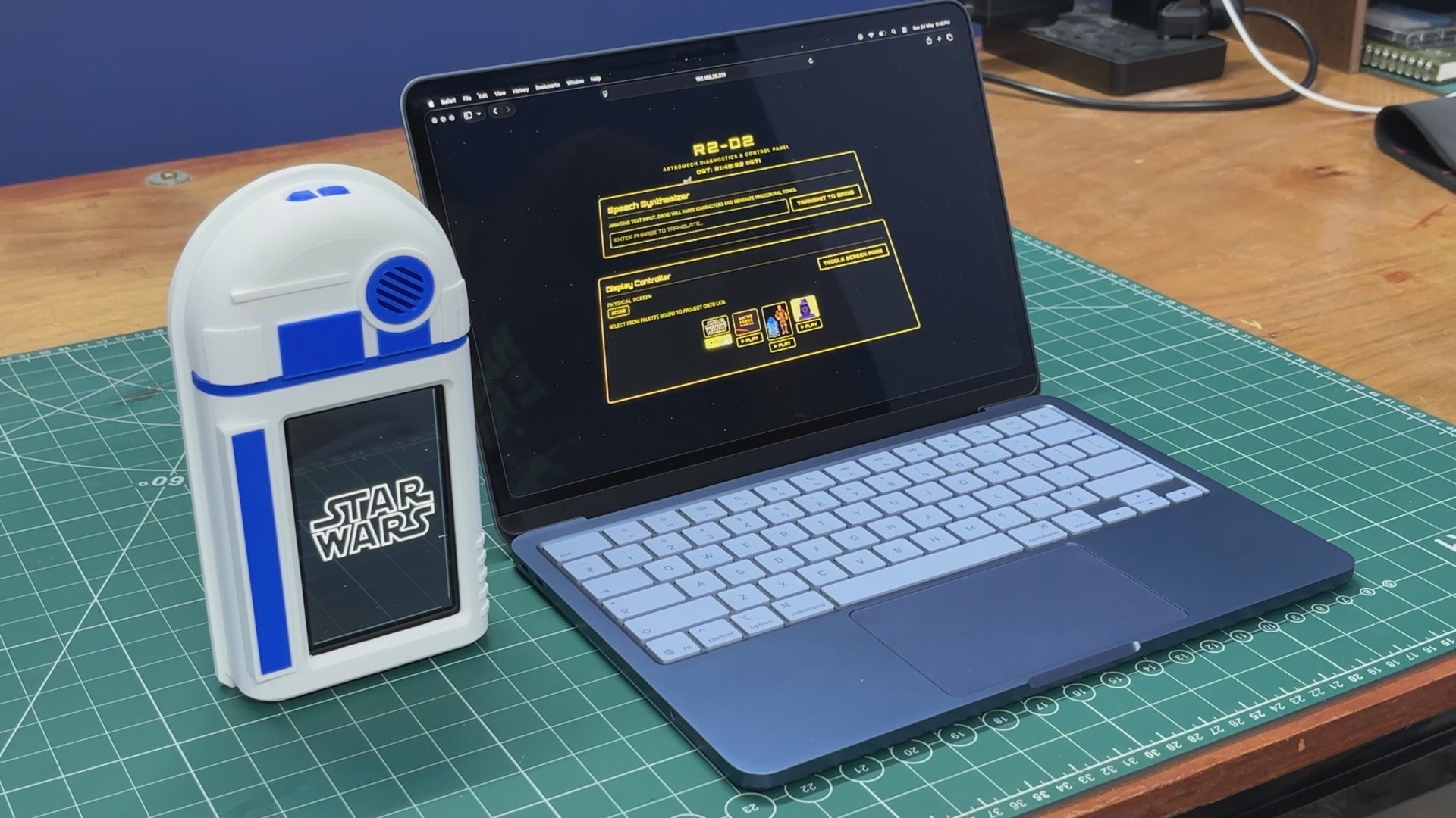
I also wanted to make it easy to use, so I added two physical buttons on top. One button (GPIO 48) triggers fun "Easter Egg" songs I coded in, like the Star Wars theme and a few others, while the second button (GPIO 47) lets me instantly toggle the screen between a Radar UI and my favorite GIFs.
The web interface is where the real fun happens. Through the app, we can play GIFs on the ESP32-P4's display, trigger a cinematic Star Wars-style quote display, or even use the text-to-astromech converter to make the droid speak any message.
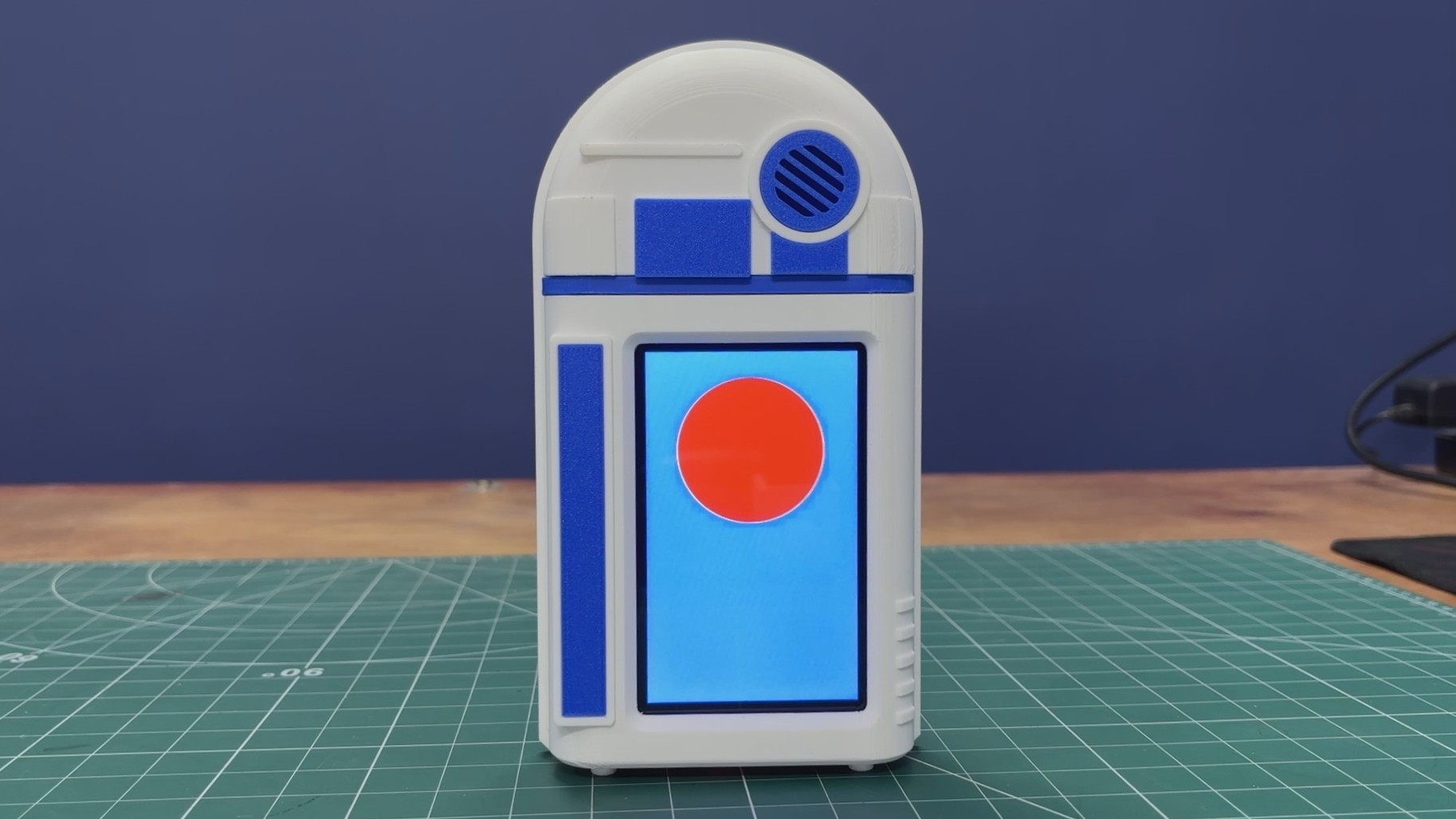
The design of this project was heavily inspired by R2-D2. Instead of creating a standard cylindrical R2-D2, I went with a flatter design that incorporates key visual elements from the original droid. The body was 3D-printed and then assembled.
DESIGN
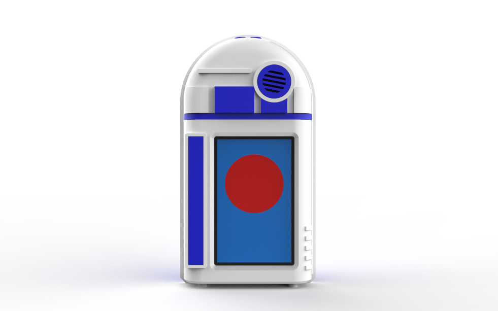
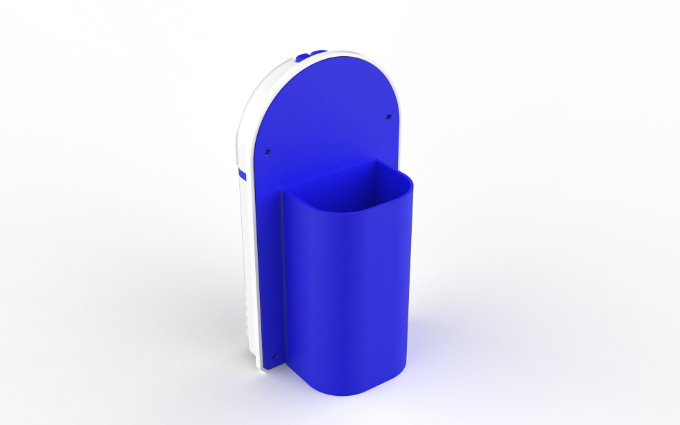
The entire model was designed in Fusion 360. While this project is heavily inspired by R2-D2, I didn't follow the original design entirely; I completely ditched the traditional cylindrical body in favor of a flat, modern aesthetic that still closely resembles the iconic droid.
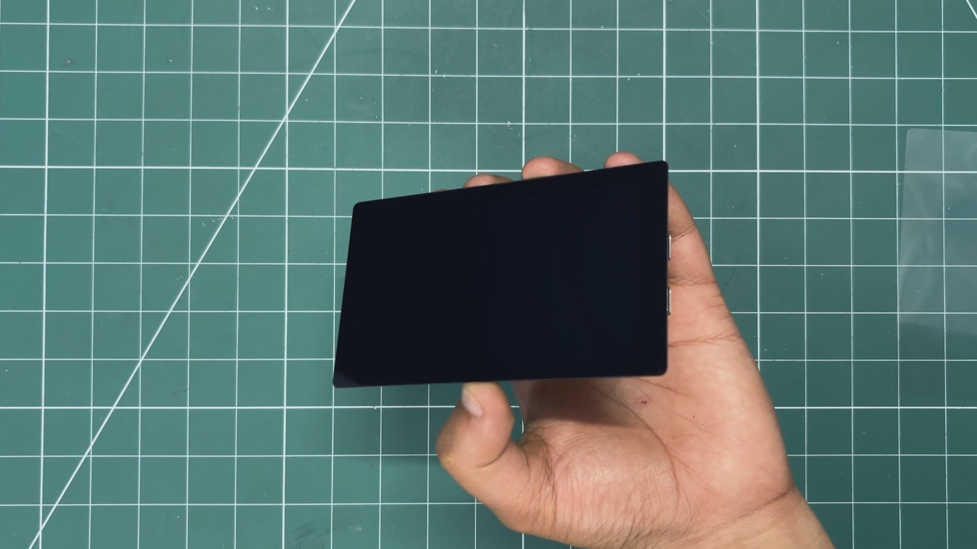
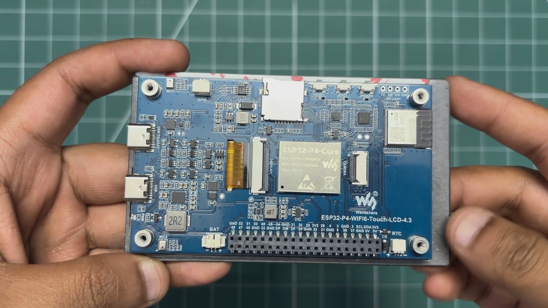
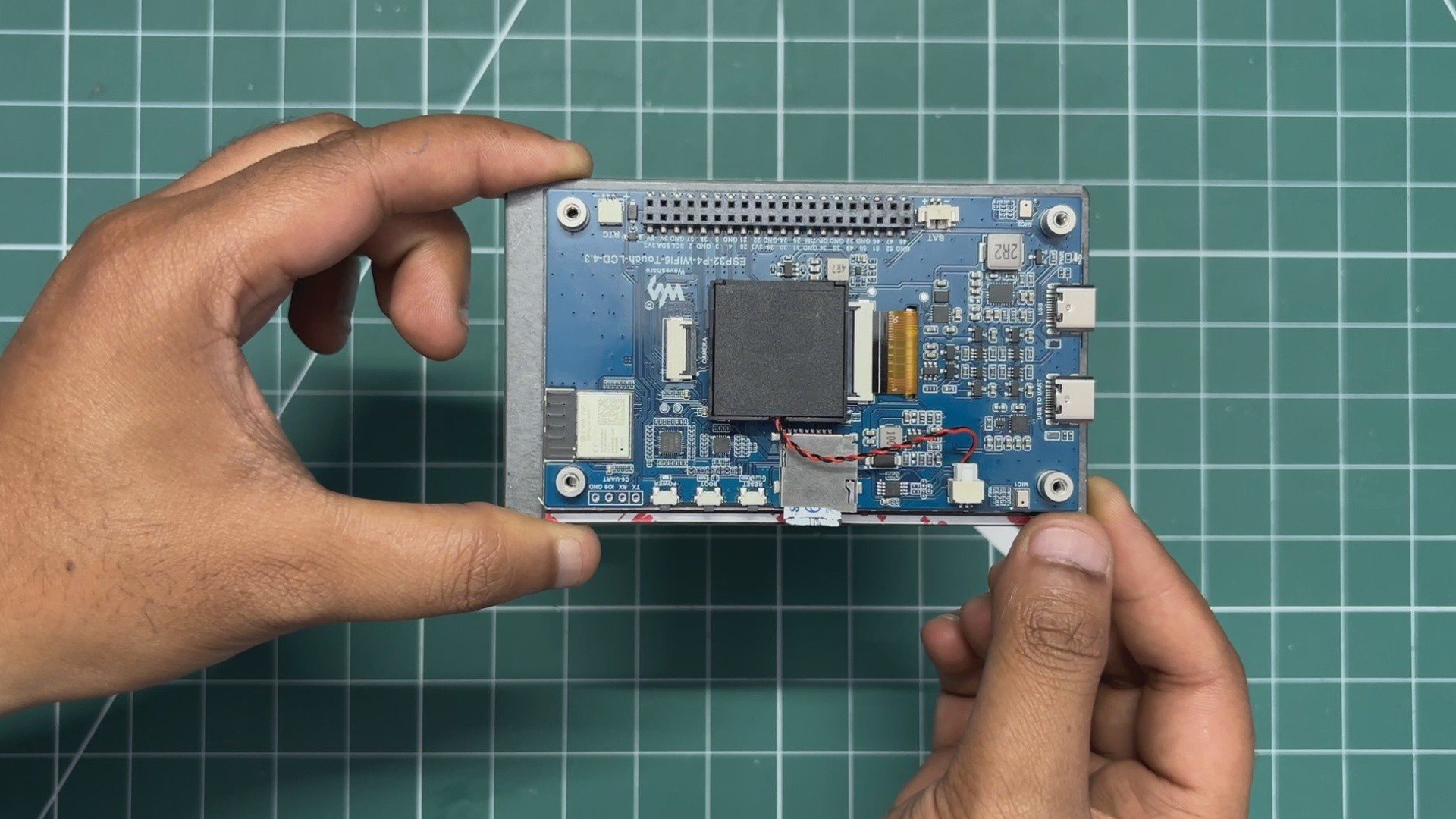
For the internals, I incorporated a Waveshare ESP32-P4 development board, which features a 4.7-inch display positioned slightly off-center. My idea is to print a blue screen on the display with a red circle that resembles R2D2.
To capture that authentic droid aesthetic, I modeled greeble parts, which I’ll be printing in blue, and the body will be printed in white.
On the back, I added a custom lid section that functions as the pen holder, making sure the device stays practical while looking the part.
ENCLOSURE
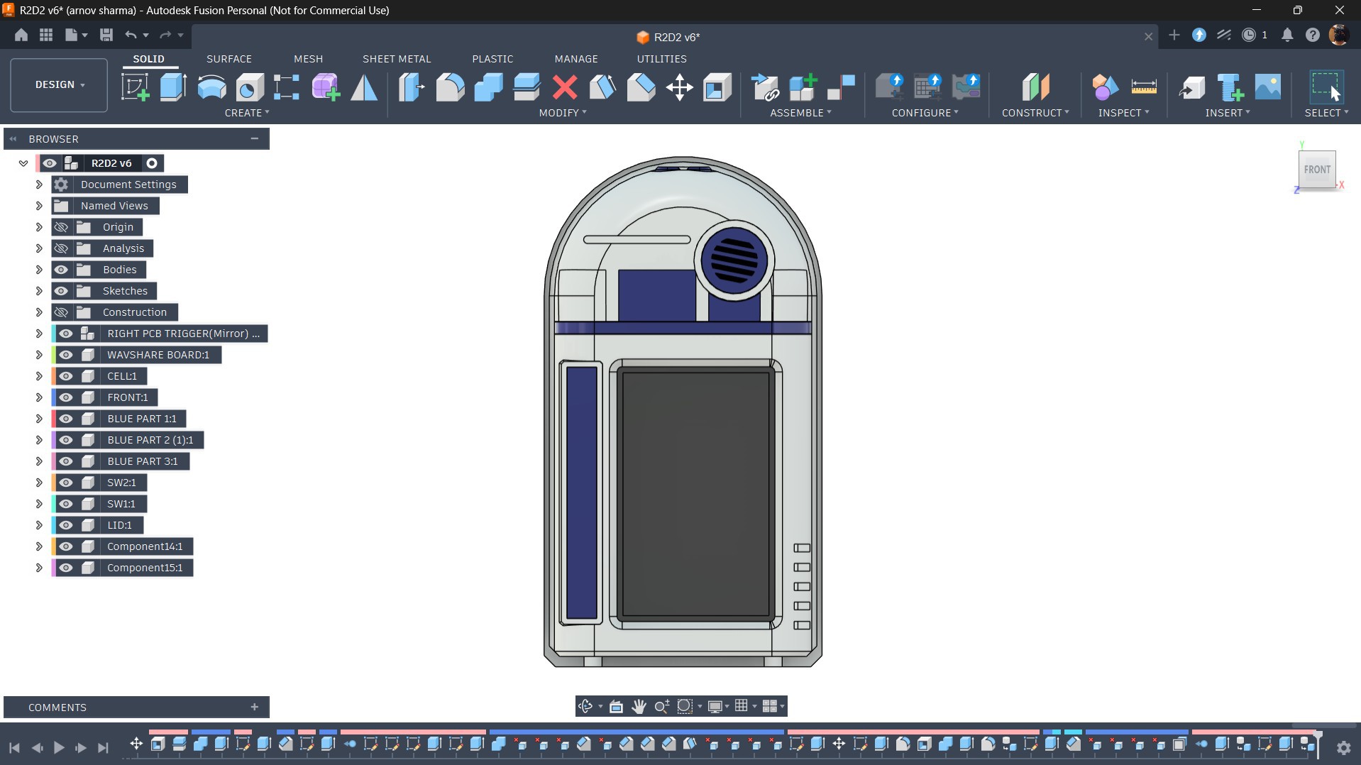
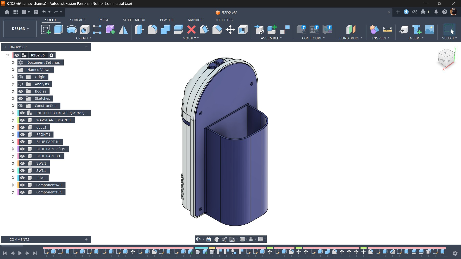
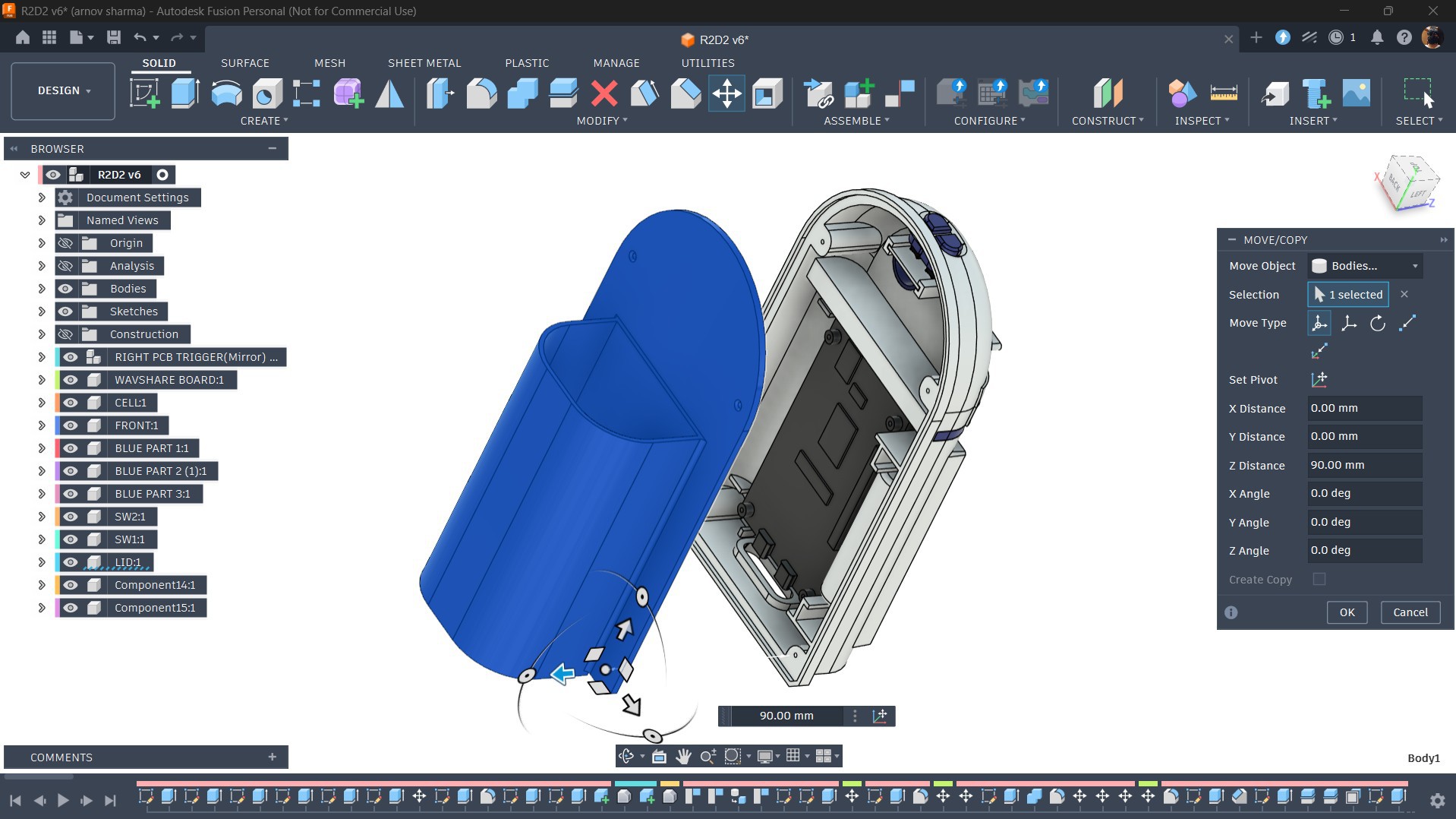
The enclosure of our design comprises two main parts: the front enclosure, which is designed to resemble R2-D2, and the back enclosure, which serves as a lid for the model while also incorporating the pen holder section.
Both the front and back enclosures are secured together using M2 screws.
SWITCH SECTION
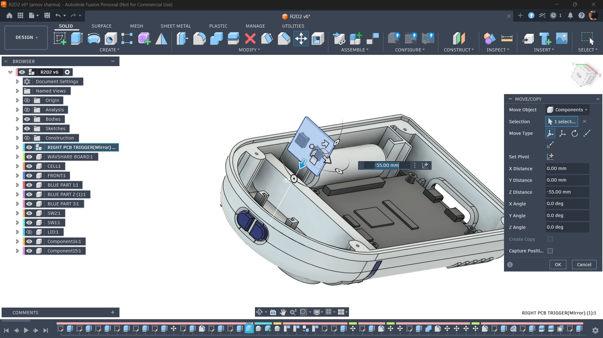
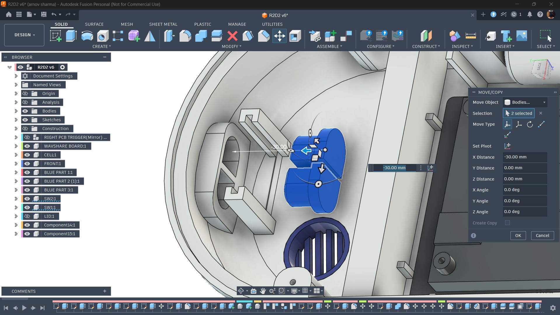
For adding controls, I incorporated two buttons into the design. The buttons are positioned on the top face of the model.
To mount them, I designed two retaining ribs that allow the switch PCB to slide into position securely. Before installing the switch PCB, two identical switch actuators are placed in their respective positions.
Once the switch PCB is inserted, the actuators are locked in place. Pressing these actuators activates the switches, registering the button press.
POWER SOURCE PLACEMENT
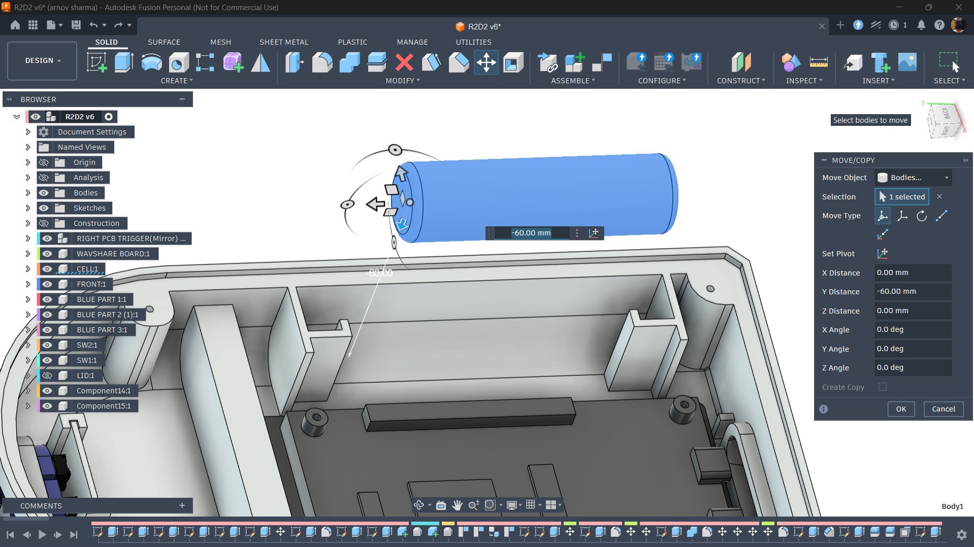
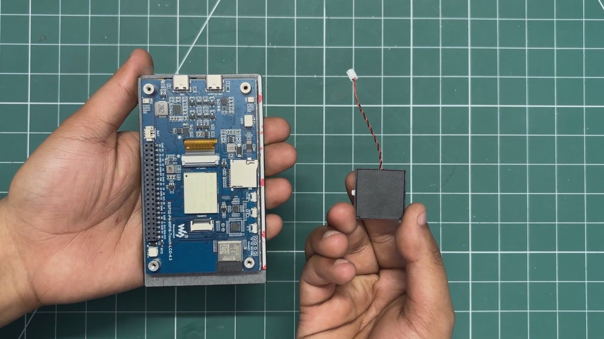
For the power source, I used a 3.7 V 500 mAh lithium-ion cell (size 14500), which is smaller than the more commonly used 18650 cell.
I positioned the battery on the opposite side of the display and added two ribs to keep it securely locked in place.
ESP32 P4 DISPLAY PLACEMENT
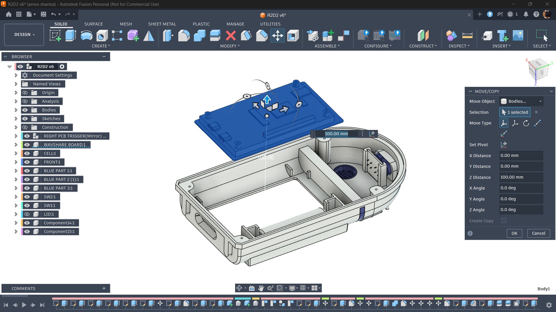
The ESP32-P4 Dev Board is placed slightly off-center. To keep it securely in position, I added several ribs that ensure the display does not move from its intended location.
GREEBLES PARTS
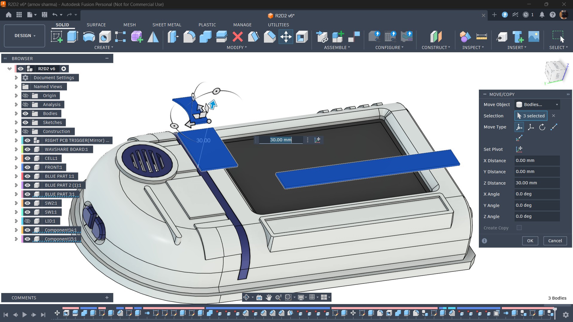
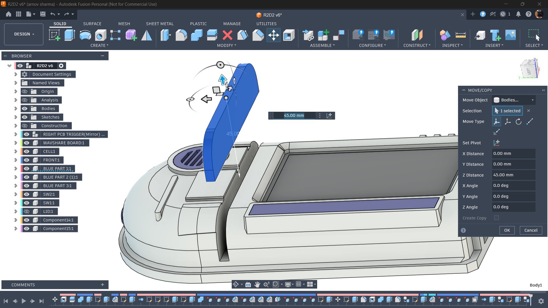
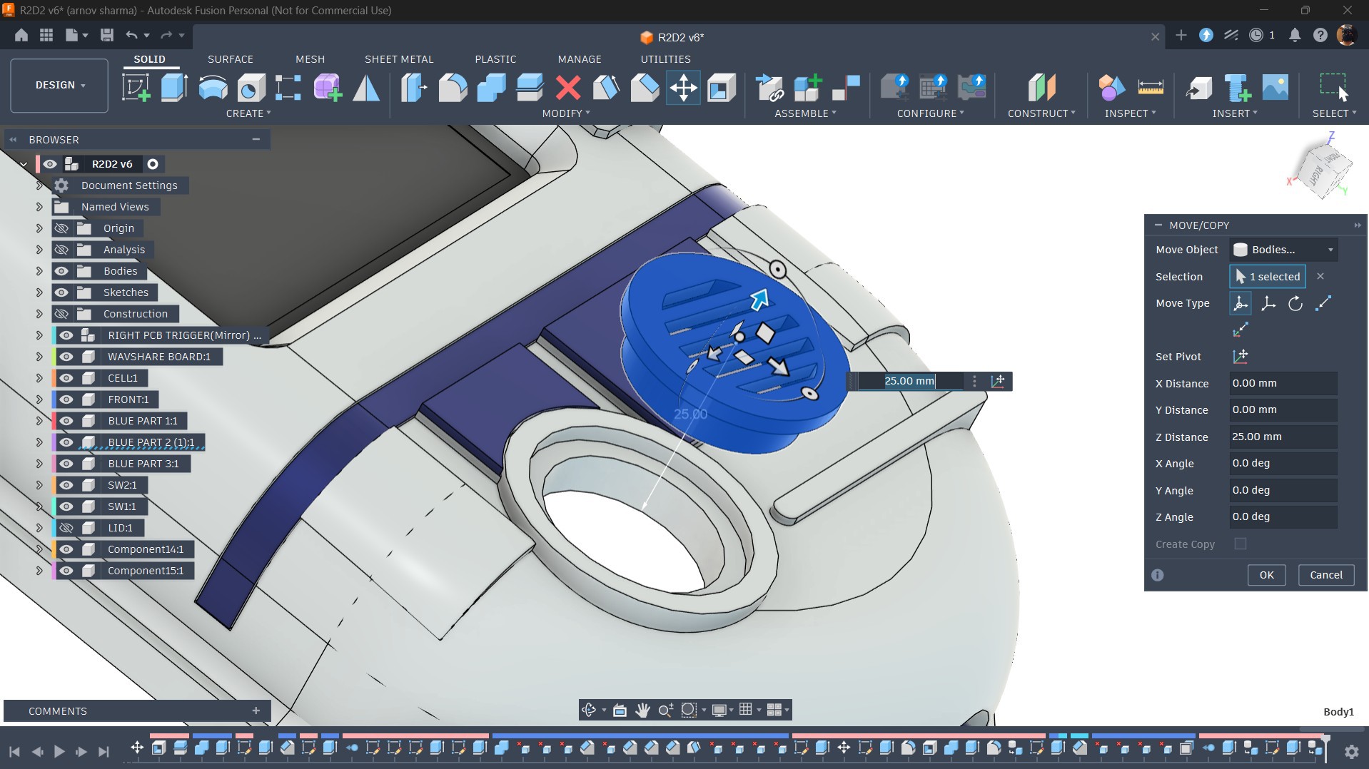
To make this device look and feel like a droid, I designed several greeble parts that would be printed in Blue PLA and then placed in position.
These include a part that sits between the screen and the head section, as well as a long part that sits next to the display.
Two additional parts are mounted on the top section slightly above the display, along with a circular grille part, all of which are printed in Blue PLA.
3D PRINTED PARTS
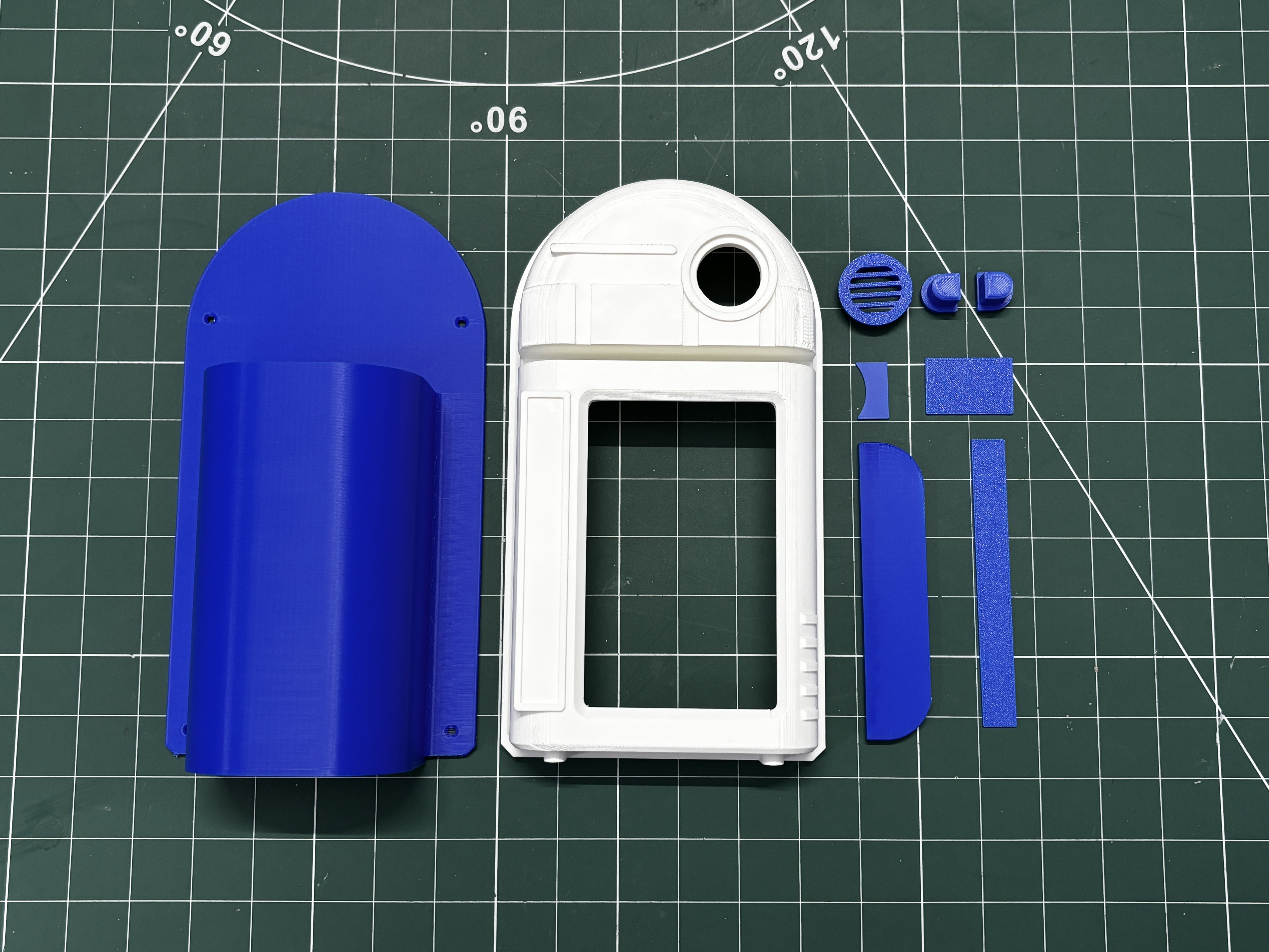
After finalizing the model, all parts were exported as mesh files and then 3D printed on my Anycubic Kobra S1 printer using two filament colors.
Blue Hyper PLA was used for the majority of the parts, including the back enclosure, greeble parts, and switch actuator.
White Hyper PLA was used for the front enclosure. All parts were printed with a 0.4 mm nozzle, 0.2 mm layer height, 25% infill, and no supports were required for the blue parts.
Only the front enclosure required supports, as it was printed upside down, so the inner parts of the model needed support.
PCB DESIGN
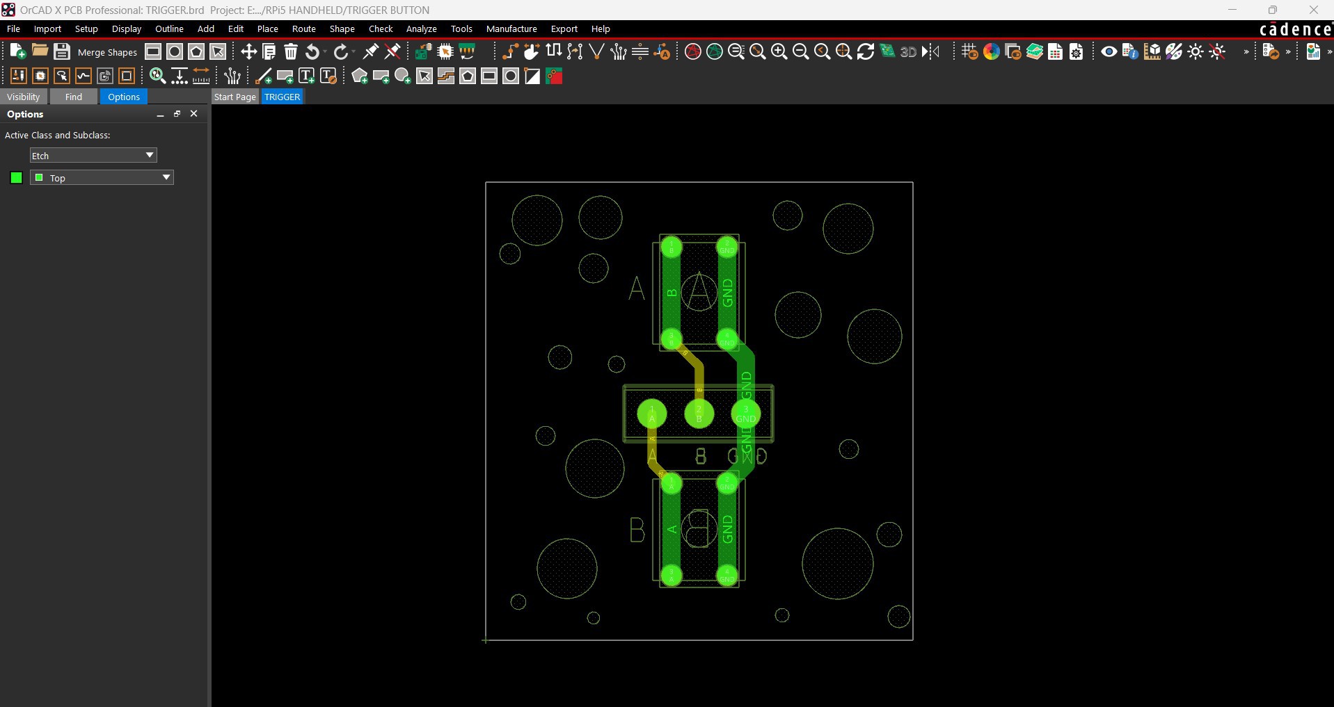
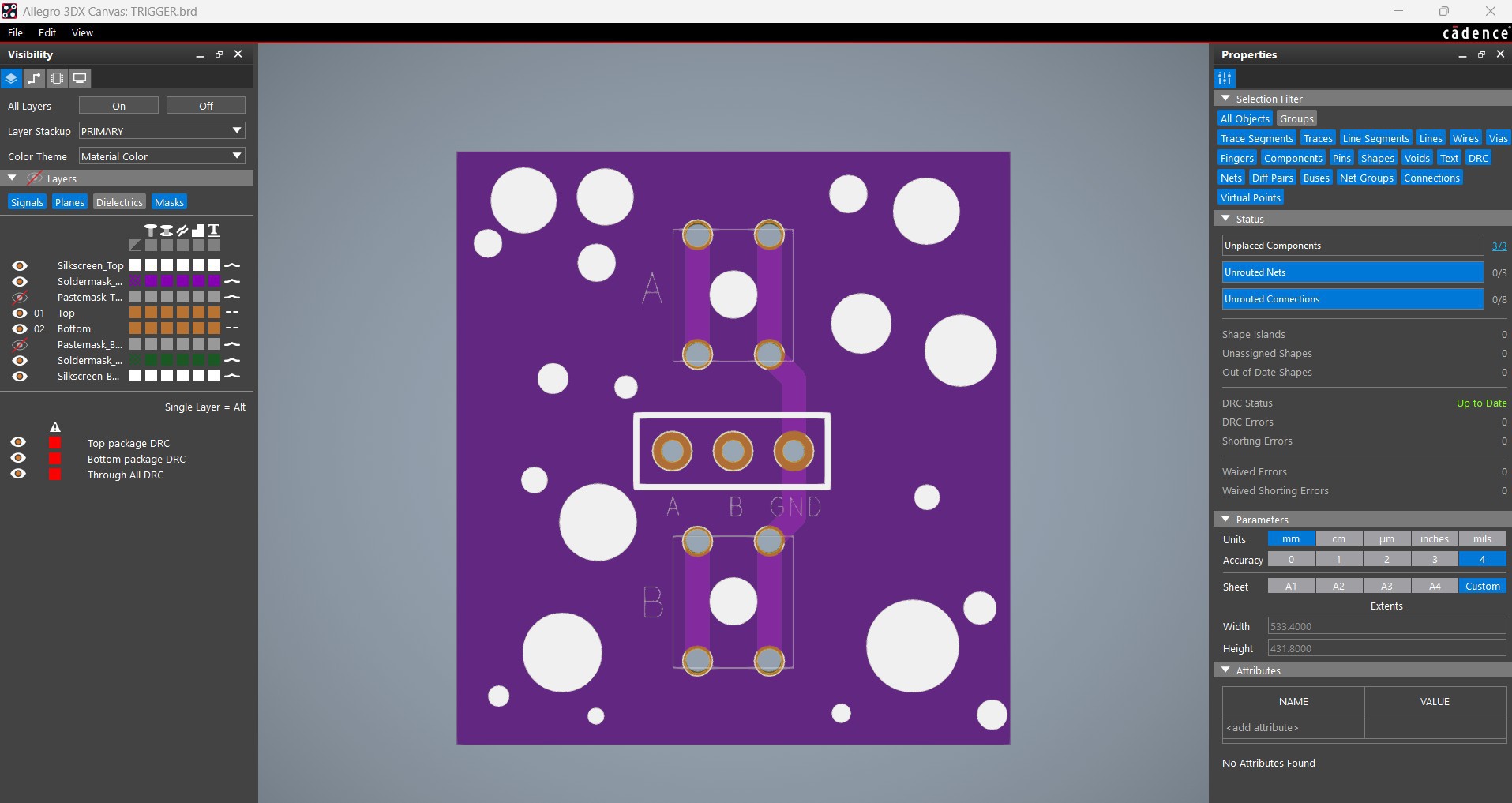
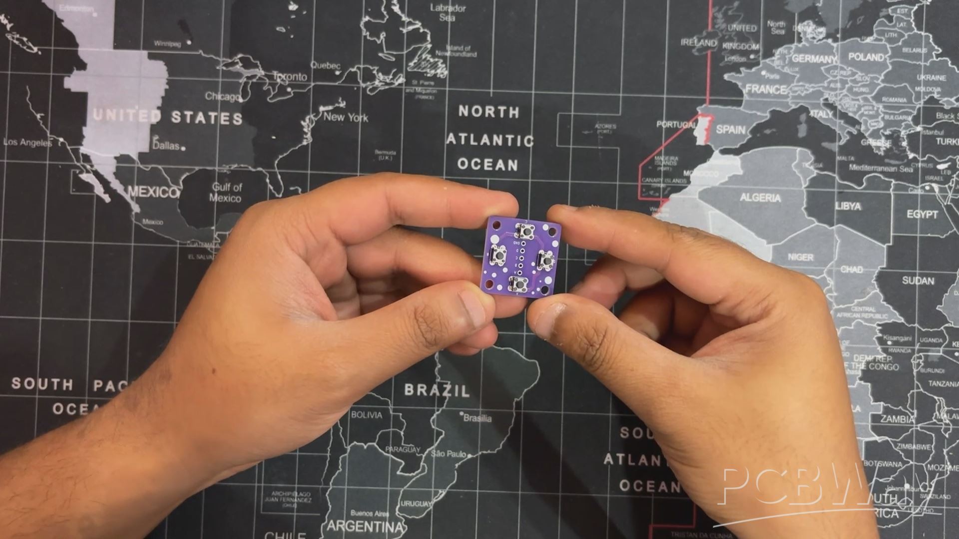
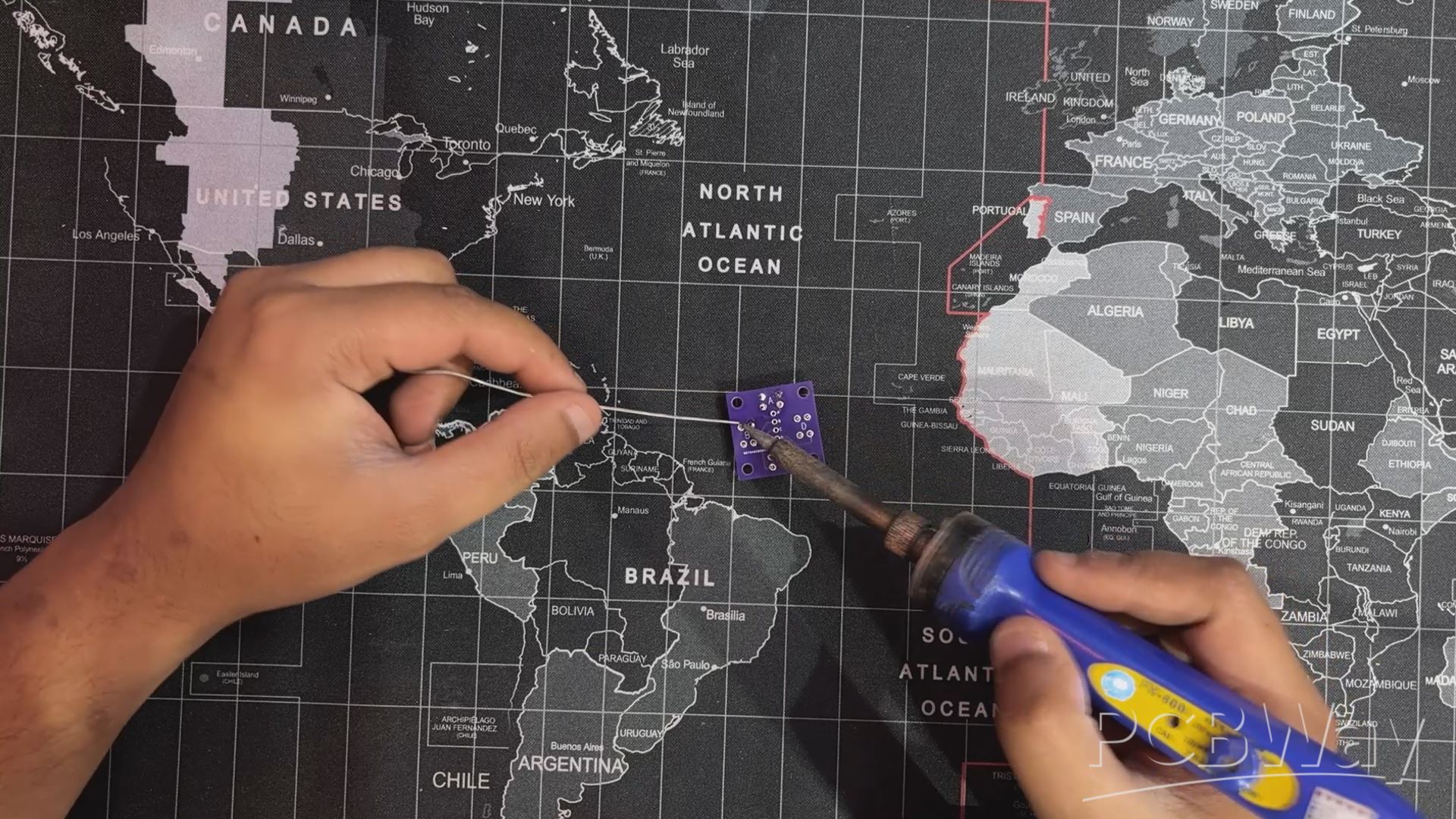
This is the Switch PCB we used in this project, and it's a simple one. Here, we have added two 4×4mm push buttons...
Read more »