 electronicsworkshops

Introduction
If you need to convert 12V, 24V, or any higher DC voltage into a stable 5V output, the LM2596 Buck Converter is one of the most reliable and efficient solutions available. Unlike linear voltage regulators, the LM2596 uses switching technology to achieve efficiencies of up to 92%, making it ideal for Arduino, ESP32, Raspberry Pi, robotics, IoT devices, automotive electronics, and battery-powered projects.
In this comprehensive guide, you'll learn how the LM2596 works, its specifications, advantages, circuit operation, applications, and how to safely configure it as a 5V DC power supply.
For Full Project:
https://electronicsworkshops.com/5v-buck-converter-using-lm2596/
For Best Electronics Calculator:
https://numericalcalculator.com/
What is an LM2596 Buck Converter?
The LM2596 Buck Converter is a high-efficiency DC-DC step-down voltage regulator that converts higher DC voltages into lower DC voltages with minimal energy loss.
Unlike traditional linear regulators that waste excess energy as heat, the LM2596 uses pulse-width modulation (PWM) switching technology to maintain stable voltage while consuming less power.
This makes it one of the most popular voltage regulator modules for electronics enthusiasts, engineers, and students.
What is a Buck Converter?
A buck converter is a switching power supply designed to reduce DC voltage while increasing efficiency.
For example:
24V → 5V
12V → 5V
9V → 5V
Instead of burning extra voltage as heat, the converter stores and releases energy using an inductor and switching transistor.
LM2596 Specifications
ParameterValueInput Voltage4V–40V DCOutput Voltage1.25V–37V AdjustableFixed Output Version5VMaximum Output Current3ASwitching Frequency150kHzEfficiencyUp to 92%Operating Temperature-40°C to +85°CProtectionThermal Shutdown, Overcurrent Protection
LM2596 Pinout
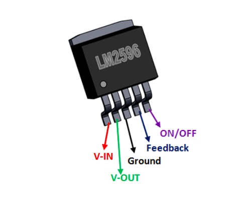
The LM2596 IC consists of five primary pins:
VIN – Input Voltage
OUTPUT – Switching Output
GND – Ground
Feedback (FB) – Voltage Regulation
ON/OFF – Enable or Disable the Regulator
On ready-made modules, the terminals are typically labeled:
IN+
IN-
OUT+
OUT-
How the LM2596 Works
The LM2596 operates using high-frequency switching at approximately 150 kHz.
Its working process involves:
The internal switch rapidly turns ON and OFF.
Energy is stored in the inductor.
The Schottky diode conducts when the switch turns OFF.
Capacitors filter the output.
The feedback circuit continuously adjusts the switching duty cycle to maintain a constant 5V output.
This process results in significantly higher efficiency compared to linear regulators.
LM2596 vs 7805 Voltage Regulator
FeatureLM25967805EfficiencyUp to 92%40–60%Maximum Current3A1AHeat GenerationLowHighInput VoltageUp to 40VLimitedCooling RequiredRarelyOftenBattery LifeLongerShorter
Circuit Diagram
The circuit shown is a 5V fixed-output buck converter based on the LM2596S-5.0 switching voltage regulator, designed to efficiently convert a higher DC input voltage (typically 7V to 40V) into a stable 5V DC output. The input voltage is applied to the VIN terminal, where the 330 µF input capacitor (C1) filters noise and voltage fluctuations before supplying power to the LM2596 IC. Inside the regulator, an internal high-speed switching transistor operates at approximately 150 kHz, rapidly switching the input voltage on and off. The 47 µH inductor (L1) stores energy during the ON cycle and releases it during the OFF cycle, while the SS34 Schottky diode (D1) provides a current path when the internal switch is off, ensuring continuous current flow and improving overall efficiency.
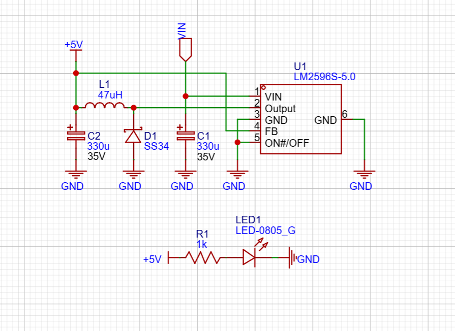
The output stage consists of a 330 µF capacitor (C2) that smooths the switching pulses into a clean and stable 5V output with minimal ripple, making it suitable for powering microcontrollers, sensors, and other electronic devices. The ON/OFF pin of the LM2596 is connected to ground, keeping the regulator permanently enabled. Additionally,...
Read more »